Source context: OSHA Technical Manual — Advanced Composites.
To cut a cured carbon-fiber composite (CFRP), use a cutting tool suited to the laminate, support the workpiece near the cut, control dust where it is generated, and inspect both faces for chipping, exposed fibers, or delamination. A fine-tooth or composite-rated saw, suitable abrasive or diamond tool, or qualified CNC process may work, depending on material, geometry, cure condition and required edge quality. The tool category does not establish a process window by itself. There is no universal blade, RPM, feed rate, or tolerance suitable for every carbon-fiber sheet.
Before choosing a tool, identify whether you have rigid cured sheet or tube, dry carbon-fiber cloth, or uncured prepreg. These are not interchangeable cutting jobs. If dust containment, machine guarding, or qualified inspection is unavailable, do not improvise a dry cutting operation; consider a properly equipped composite shop.
Start by identifying the material
Dry fabric is flexible reinforcement. It may be cut with textile shears or a suitable knife system, taking care not to pull the weave out of alignment. Prepreg is reinforcement carrying uncured resin and may require controlled storage, handling and layup precautions; it should not be treated as fully cured stock.
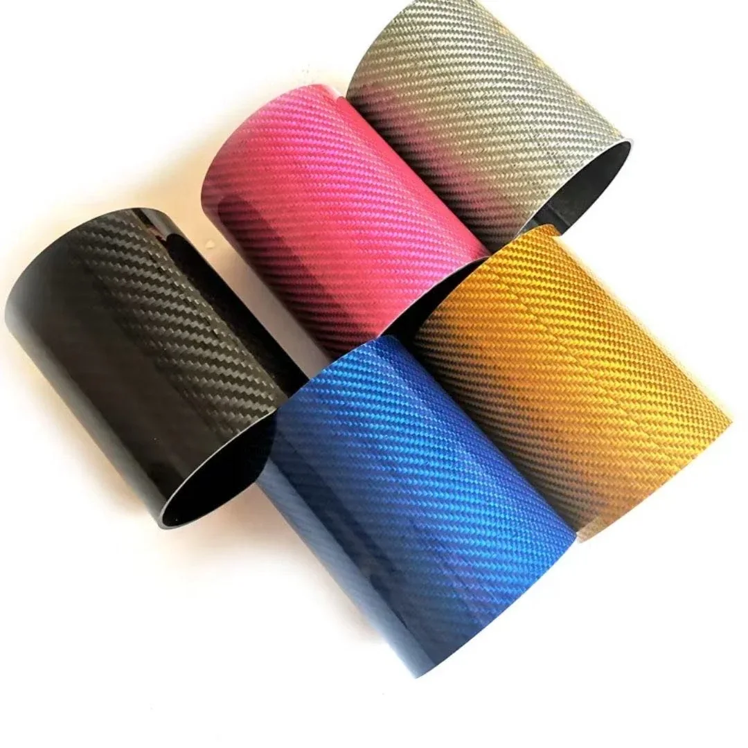
A cured CFRP sheet or tube is a solid composite. Cutting it means fracturing fibers and the cured matrix together. The consequences can include airborne fine particles, sharp fragments, local heat, resin smearing, fiber pull-out and subsurface layer separation. Tool advice for cloth or uncured prepreg should not be transferred to a rigid panel.
Check the material supplier’s current safety data and processing guidance, including coatings or fillers that can alter dust composition. If the sheet contains a foam/honeycomb core, other reinforcements, surface coating, metal insert or unusual resin, the correct cutting plan can change.
Safety comes before tool selection
Machining a cured laminate can create airborne composite dust and fine fibers. The hazards depend on the material and the operation; no visual check alone demonstrates that an exposure is acceptable. Occupational guidance from OSHA and Monash University makes risk assessment and exposure control central to this work.
A practical workshop review should address the following before the cut begins:
- Engineering controls: An enclosure, extraction at the cutting point, or another appropriately designed source-capture system should manage airborne debris. A standard shop vacuum, an open window, or an improvised mask is not proof of adequate control. Confirm source-capture performance for the specific operation and maintain collectors/filters under the equipment’s documented service procedure.
- Conductive contamination: Carbon-containing dust can reach exposed electronics or electrical connections. Consider the machine, controls and nearby equipment in the isolation and cleaning plan; use qualified electrical and dust-system personnel for design decisions.
- Guarding and fixturing: Use a suitable guarded machine and a support method that prevents movement or crushing. Do not defeat guards to improve access.
- Eye, skin and respiratory protection: Choose protection from a site-specific assessment and the applicable safety requirements. Where respirators are required at work, a compliant respiratory-protection program may be needed; a suggested filter label is not a substitute for this assessment.
- Cleaning and waste: Collect debris using an appropriate dust collection or controlled wet method. Avoid dry brushing or compressed air that redistributes particles. Treat slurry, filter waste and contaminated wipes in accordance with material data and local requirements.
Wet methods can suppress some dust and heat, but introduce liquid handling, electrical and wastewater concerns. They are not automatically safer for a particular machine, composite or downstream bonding operation. If controls fail, the part moves or visible dust escapes, stop, secure the equipment and resolve the condition before restarting.
These are general engineering considerations, not a statement that any particular CFRPWorks machine or workplace has passed a safety assessment.
Choose a cutting method for the part, not the material name
The following table compares common categories of options. Actual tool selection must follow the manufacturer’s guidance for the cured laminate, guard and equipment, plus a controlled trial on representative offcut stock using the same support and intended edge requirement.
| Job | Possible approach | Main limitation to assess |
|---|---|---|
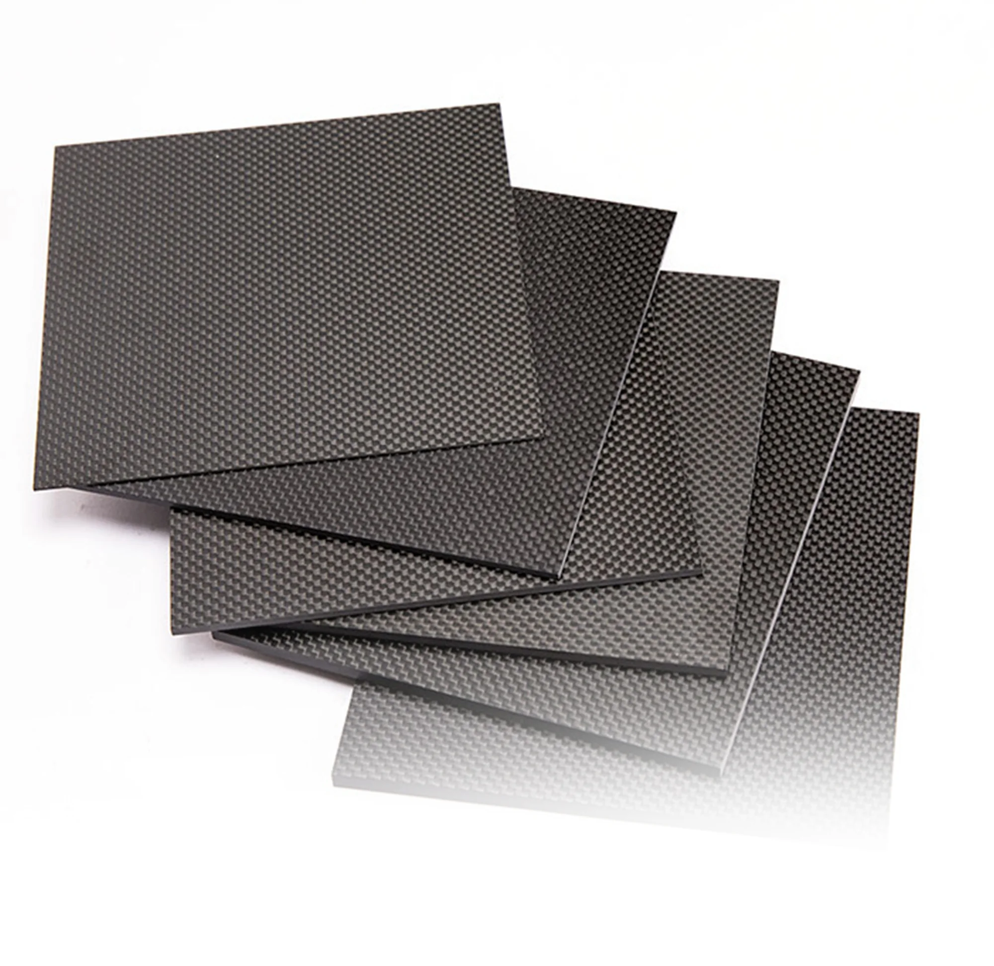
| Straight edge in cured sheet | Suitable fine-tooth saw, abrasive wheel or composite-rated cutting blade | Exit-face breakout, heat, uncontrolled dust and support |
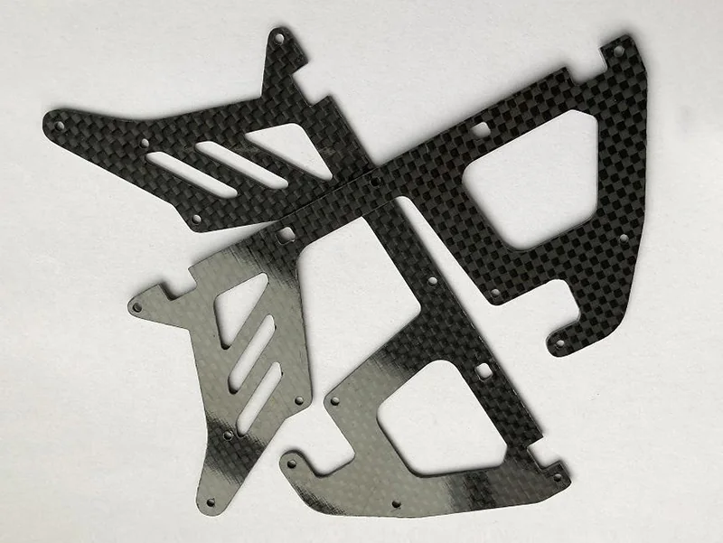
| Small trim or shaped opening | Controlled rotary or abrasive tool in an appropriate fixture | Vibration, edge chipping, tool wear and close source capture |
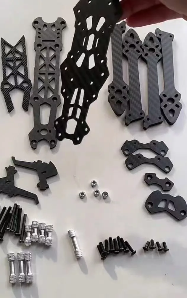
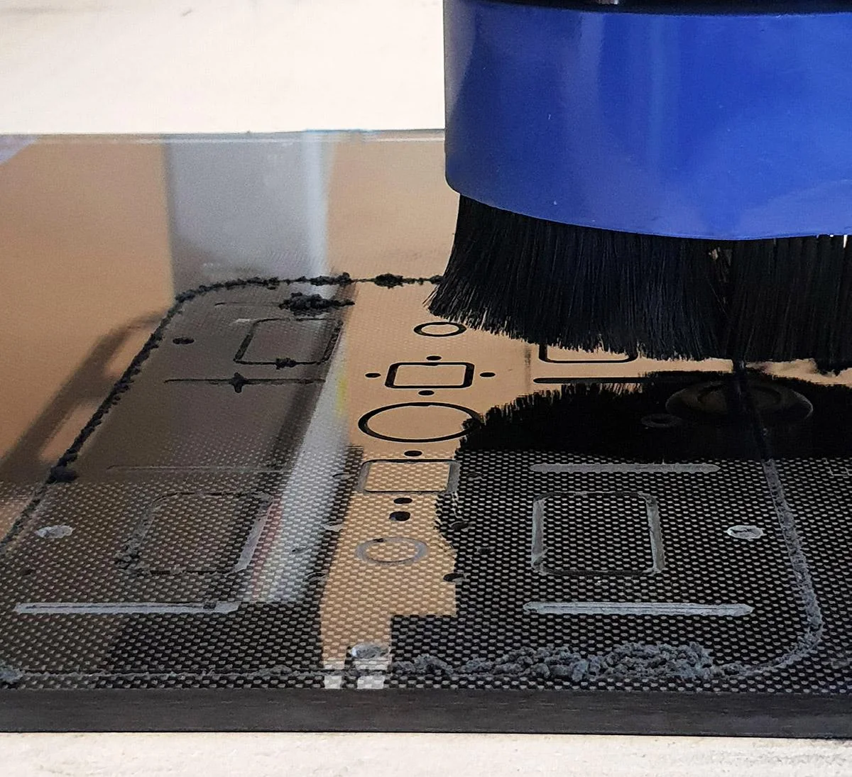
| Repeating profiles or holes | CNC router/mill with composite-specific tool and qualified workholding | Delamination at entry/exit, positional accuracy, dust handling and cutter wear |
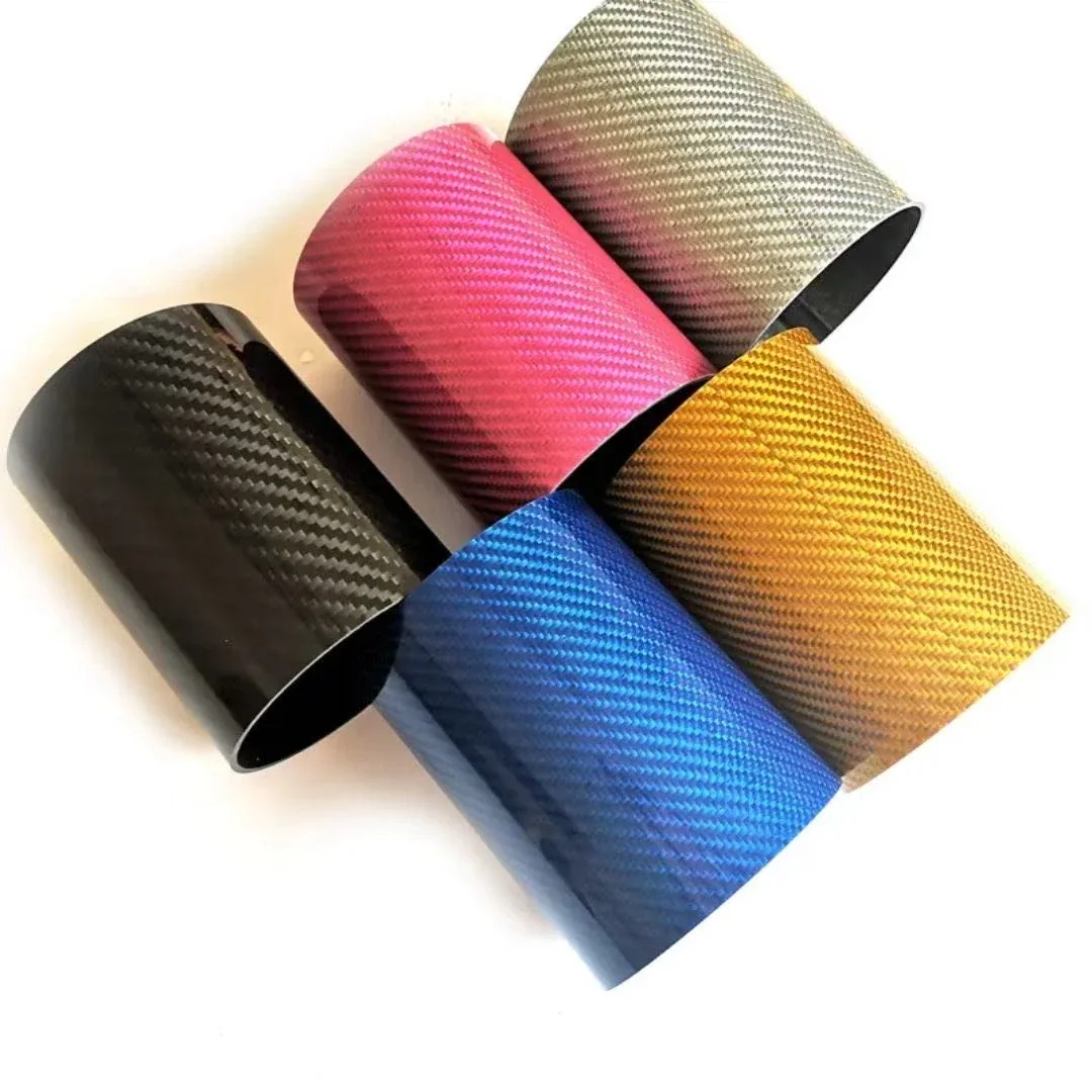
| Tube cut to length | Supported, suitable saw or abrasive cut-off process | Tube ovalization, splitting at breakthrough and end squareness |
| Complex or thick profiles | Specialist machining or assessed abrasive-waterjet process | Kerf/taper, pierce damage, edge roughness, contamination and processing access |
| Dry carbon-fiber cloth | Sharp shears or a textile-cutting system | Distorted weave, displaced fibers and cut pattern accuracy |
Abrasive and diamond-type cutters may be suitable for CFRP’s abrasion-heavy cutting conditions, but they still need tool-specific machine compatibility, containment, wear monitoring and edge evaluation. “Diamond” is not a guaranteed clean-cut label. Likewise, a waterjet has low thermal input yet still requires validation for pierce marks, surface integrity, taper and water management.
Do not borrow generic “best speed” or “best bit” values from a product advertisement without verifying the exact laminate, cutter geometry, machine and target quality.

A controlled workflow for cutting a cured sheet
1. Establish what the finished feature must do
Use the drawing to identify the stock format, thickness, fiber direction if known, cut line, hole positions and tolerances. Mark whether the cut edge is cosmetic, forms a seal, receives a fastener or will be bonded. A load-bearing edge needs stronger acceptance criteria than a nonstructural trim.
For hole and slot patterns, discuss minimum edge distances and local loads with the responsible designer. Dimensional accuracy is one quality criterion; it does not establish whether fibers were damaged, the part remains sufficiently strong, or the joint design is adequate.
2. Secure the laminate without bending it
Support the work near the cutting zone so it cannot vibrate or bend away from the tool. A compatible sacrificial backing surface can help protect the underside on some cuts. For tubes, support both sides and prevent rotation or crushing.
A fixture that keeps the part flat but contaminates a future adhesive interface is not automatically acceptable. Check tapes, protective films, coolant and clamping marks against the finishing and bonding plan.
3. Qualify the tool and process on representative material
Follow tool and machine manufacturer directions for the specific material. Trial the intended cutting approach on an offcut that matches the actual sheet or tube in thickness, orientation and surface finish. Watch for chatter, fiber fraying, scorching, melting/smearing resin, accelerated tool wear, surface cracking or layer lift on both faces. Do not accept a trial merely because the top face looks clean.
Use trial inspection to decide whether to adjust support, tool condition, toolpath, pass strategy, or a manufacturer-supported machine parameter. Record the condition that produces an acceptable part. A published setting from a different laminate is not a process qualification.
4. Control dust and prevent uncontrolled breakthrough
Maintain suitable source capture throughout cutting, final breakthrough and debris collection; controlled cleanup should begin only when the moving tool and extraction arrangement are safely managed. Hold the retained piece and offcut securely. Maintain guards, keep bystanders out of the work area, and stop if the process starts to damage material or overwhelm the controls.
5. Inspect, clean and record the finished feature
After safe debris removal, inspect both sides and the cut edge for fuzzing, pull-out, cracks, exposed plies, delamination and heat discoloration. Measure profiles, hole size and position, edge squareness or tube end quality as required by the drawing. For a future bond, follow the adhesive or process specification rather than assuming the as-cut surface is ready to join.
If an edge carries significant load or lies near an insert, visible appearance may not establish acceptance. The responsible engineer should define any additional measurement or nondestructive inspection.
Why carbon fiber edges chip or delaminate
A cutting tool does more than remove a line of material. It loads fibers and the matrix differently as the contact direction changes. The abrasive nature of fibers accelerates some kinds of cutter wear; increasing force and vibration can create defects.
| Observed issue | Potential cause to investigate | Engineering response |
|---|---|---|
| Fuzzy or loose fibers | Tool geometry, dull edge, unsupported fiber direction | Reassess cutter condition and support; inspect for underlying damage |
| Exit-face chipping | Weak backing, excessive breakout forces or movement | Improve compatible support and requalify breakthrough |
| Visible ply lift | Interlaminar loading or a damaging toolpath | Reject or evaluate against the part’s damage criteria; change process |
| Resin smear or discoloration | Local frictional heating or worn tooling | Stop, assess thermal damage and qualify cooling/tool choices |
| Hole damage or wrong position | Fixture shift, thrust or tool runout | Re-evaluate fixture, hole method and dimensional inspection |
A peer-reviewed study of composite machining particles documents small fibrous fragments as well as larger debris. Its specific laboratory particles do not establish exposure at another shop. The precise distribution of debris depends on the tested operation; the paper cannot be converted into a universal safe cutting limit.
When CNC machining or custom cutting becomes the better next step
The question is not whether a hand tool can remove material; it is whether a complete and safely controlled process can meet the print. It is whether the team can repeatedly meet the required geometry, edge quality and workplace controls.
A drawing with several close-positioned holes, complex contours, insert interfaces or an edge critical to fatigue may require a qualified machine process, fixtures, inspection and documented revision control. A simple prototype trim might have a different acceptance target. Neither case comes with an inherent tolerance guarantee merely because it uses CNC.
If the desired outcome is an outsourced operation, keep the buying tasks distinct: CNC capability evaluation belongs to the planned Carbon Fiber CNC Machining capability page; dimension-specific flat blanks belong to the Custom-Cut Carbon Fiber Sheets product page. This article remains a how-to and process-selection guide.
A useful cutting request includes the drawing/CAD file and revision, actual material/resin and thickness, fiber architecture when known, quantities, required edge/appearance grade, hole details, mating parts, end-use load and inspection criteria. Those inputs help a qualified processor assess a method, but do not prove that a specific supplier has accepted the job.
Frequently asked questions
Can I cut a carbon-fiber sheet at home?
A cured composite can be machined, but uncontrolled cutting can expose people and electronics to fine, potentially conductive debris. If proper guarding, material-specific controls, ventilation, PPE assessment and cleaning are not available, use an appropriately equipped professional service rather than assuming a small hand tool is safe.
What is the best blade for cutting carbon fiber?
There is no universal best blade. The answer depends on cured resin, thickness, fiber architecture, cut type, fixture and the equipment. Even similar nominal carbon-fiber stock can behave differently when the matrix or layup changes. Composite-rated abrasive or diamond-type tools and suitable fine-tooth cutters are possible starting categories, subject to vendor instructions and trial inspection.
Can I use a CNC router to cut carbon fiber?
CNC routing is a recognized method for cured CFRP when tooling, fixturing, process parameters, dust extraction and inspection are qualified for the material. A router does not automatically guarantee a tolerance, clean edge or a safe environment.
Does cutting carbon fiber weaken it?
It can, especially where a cut leaves delamination, exposed fibers, heat damage or new stress concentrations near a loaded hole or edge. Properly designed, controlled and inspected trimming is a normal manufacturing operation; whether a given cut meets the structural requirement depends on the specific geometry and evidence.
Can I use water to keep the dust down?
Wet processes can reduce some airborne dust and heat, but water, slurry, equipment compatibility, contaminated waste and later adhesive or coating operations require their own assessment. Use only a process intended for the equipment and composite.
Move from cutting advice to a drawing-based decision
For dimension-specific flat blanks, see the custom-cut carbon-fiber sheets product page. For broader project process questions, see custom manufacturing. These pages cover buying decisions rather than the safety and method selection explained here.
View Related Product / Capability: Define whether your need is an educational one-off trim, repeated CNC profiling, or a dimension-specific carbon-fiber sheet. Prepare a drawing, material identification, edge and hole requirements and inspection criteria before discussing a cutting service. Any CFRPWorks production method, acceptance tolerance, availability or quote must be confirmed separately for the actual project.
Related technical guides: Carbon Fiber Strength & Properties · Carbon Fiber Sheet Thickness Guide. Related product / capability: Carbon Fiber CNC Machining · Carbon Fiber Sheets.
References
- OSHA Technical Manual — Advanced Composites
- Monash University — Carbon Fibre Composites Safety Information
- DragonPlate — How to Cut Carbon Fiber
- Elevated Materials — Cutting Carbon Fiber by Hand
- ToolsToday — Cutting Carbon Fiber on a CNC
- CompositesWorld — Industrial Dust Mitigation
- Peer-reviewed Study — Composite Machining Debris (PMC)