Source context: Toray Composite Materials America — Carbon Fiber Grades and Properties; Toray T700S Data Sheet; ASTM D3039/D3039M.
Carbon fiber does not have one universal tensile-strength value. A number can describe a bare reinforcement fiber, a cured composite laminate tested in one direction, or a finished component under a defined load case. Those are different evidence levels, and none can be substituted for another without engineering justification.
Quick answer: if you are asking “what is the tensile strength of carbon fiber?”, first ask what was tested. Manufacturer fiber data can reach several thousand MPa, while a cured laminate can report a different value because resin, fiber volume fraction, layup, orientation, manufacturing quality and test conditions all influence the result. A finished part adds geometry, holes, joints and real load paths, so its allowable load cannot be read directly from a fiber datasheet.
The practical question is therefore not simply “how strong is carbon fiber?” It is: strong under which load, in which direction, in what form, and proven by which test?
What Is the Tensile Strength of Carbon Fiber?
Tensile strength is the stress reached when a specimen fails in a specified tensile test. It is not the same as tensile modulus, which describes elastic stiffness, and it is not a safe working load for a finished component.
Toray lists approximately 3,530 MPa tensile strength for T300 fiber and 4,900 MPa for T700S fiber, while both are listed at approximately 230 GPa tensile modulus. These are manufacturer fiber properties. They are useful for comparing identified reinforcement grades, but they are not generic CFRP laminate values and they are not CFRPWorks product ratings.
First, distinguish strength, stiffness, and weight
Tensile strength describes the stress reached at failure under a specified tensile test. Tensile modulus, often called Young’s modulus, describes resistance to elastic stretching before failure. A material can be relatively stiff without having the highest ultimate strength, or strong without having the highest modulus.
Density describes mass per unit volume. When engineers divide strength or modulus by density, they obtain a specific strength or specific stiffness comparison. Those ratios help frame weight-sensitive material comparisons, yet they do not account for real dimensions, local joints or supports. A tensile ratio cannot predict a joint’s bearing strength or a thin panel’s buckling resistance.
| Property | Question it helps answer | What it cannot establish alone |
|---|---|---|
| Tensile strength | How much axial tensile stress did a tested specimen sustain? | Compression, shear, impact or fastener performance |
| Tensile modulus | How much does the specimen elastically stretch under tensile load? | The maximum load before failure |
| Density | What mass results from a given material volume? | Overall assembled weight or efficiency |
| Flexural behavior | How does a specified plate or beam respond in bending? | A universal “carbon fiber strength” grade |
| Electrical behavior | Can the fiber network form a conductive path? | Resistance of every finished laminate or joint |
Fiber Strength Is Not Laminate Strength
A carbon-fiber supplier’s datasheet may report extremely high strength for the bare filaments. That is useful when choosing reinforcement, but the buyer usually receives a polymer-matrix composite, not a bundle of isolated filaments.
| Evidence level | Typical information | Suitable engineering conclusion |
|---|---|---|
| Fiber or tow datasheet | Manufacturer grade, bare-fiber tensile strength and modulus, density, filament/tow details | Compare reinforcement candidates; not a finished-part rating |
| Cured laminate coupon | Fiber and resin identity, stacking schedule, fiber fraction, orientation, specimen, test conditions and failure mode | Characterize the particular material and direction tested |
| Finished component and its joints | Actual drawing revision, critical geometry, inserts, load case, inspection and part-level validation | Assess whether the specific design is fit for its intended load path |
Toray’s T700S data sheet shows why the evidence level matters. It lists 4,900 MPa tensile strength for the T700S fiber itself. The same data sheet separately lists example composite tensile properties under stated conditions, including about 2,860 MPa longitudinal tensile strength and about 81 MPa at 90°. Those composite figures are normalized to 60% fiber volume and use the stated epoxy cure conditions; they are not universal T700S laminate values.
The contrast is the point: the phrase “carbon fiber tensile strength” is incomplete unless the material form, laminate construction, load direction and test conditions are known. None of these Toray figures states that a CFRPWorks panel contains T700S, or that a CFRPWorks finished part will reproduce the listed fiber or composite result.
The gap between the three evidence levels matters whenever a brochure is used to justify a real drawing or safety factor. Resin binds fibers, transfers load between them, and influences transverse and shear response. Manufacturing details affect fiber alignment, wet-out, resin distribution, voids and adhesion; those variables help explain why nominally similar reinforcement can yield different coupon results. The finished shape adds holes, edges, corners and joints that are absent from a simple straight coupon.
Why fiber orientation changes the answer
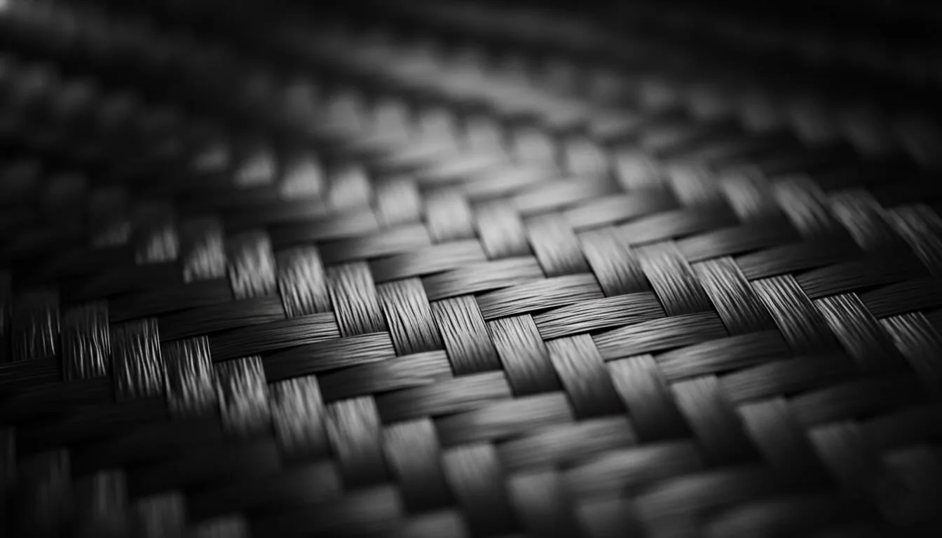
Carbon-fiber-reinforced polymer (CFRP) is generally direction-dependent, or anisotropic. A unidirectional ply loaded along its fibers (often called 0°) behaves differently from the same material pulled across the fibers (90°). Plies oriented around ±45° are often selected when in-plane shear or torsion is significant.
A laminate commonly combines orientations to satisfy several loading directions. Symmetry and ply order also affect bending–twisting coupling and where interlaminar stress is concentrated. However, “more 0° fibers” is not an automatic design rule: the structure might need transverse stiffness, buckling resistance, symmetric stacking, bearing strength around holes, or reliable bonded joints. Woven and multidirectional laminates can distribute reinforcement among directions, but their usable properties still require configuration-specific evidence.
This is why a single tensile-strength number should not be treated as an isotropic property of every carbon-fiber laminate.
Imagine two parts made with nominally similar carbon-fiber reinforcement. One is a flat tie loaded approximately along continuous fibers. The other is a bracket with a bolt hole and a changing load angle. The first may be dominated by axial tension; the second introduces bearing stress, local shear, stress concentration, and possible splitting or delamination. A single 0° tensile value cannot rate both. Hole diameter, edge distance and fastener support become part of the acceptance requirement.
Published laminate studies illustrate the influence of ply angle and stacking sequence on measured strength and stiffness. They do not provide transferable test results for every supplier’s plate or part.
Why a Finished Carbon-Fiber Part Can Fail Below a Fiber Datasheet Number
Compression and buckling. A thin or long component may deform or buckle before reaching its material tensile limit. Fiber waviness, unsupported length, face-sheet support and geometry can matter even when a tensile datasheet looks attractive. Bending stiffness cannot be inferred from bare-fiber modulus without a section and layup.
Shear and delamination. Polymer matrices and fiber interfaces help transfer load among plies. Interlaminar stresses near corners, holes, cutouts and thickness changes may determine the failure mode.
Impact and fatigue. A surface that looks intact can hide damage after impact; repeated loading may also change the allowable design envelope. Neither issue is answered by one monotonic tensile test.
Heat and moisture. Matrix chemistry, cure and environmental conditioning affect how much measured performance may be retained in service. The applicable temperature, chemical exposure and moisture history belong in the design brief.
Electrical contact. Carbon fibers themselves are electrically conductive. A finished composite’s conductivity depends on whether its fibers form connected pathways, how resin interrupts those paths, ply orientation and contact geometry. Conductive fibers also call for a galvanic-contact review when joined to susceptible metals in an electrolyte; a joint may require electrical isolation. Do not treat every CFRP laminate as an electrical insulator or infer a reliable grounding path solely from its fiber label.
These behaviors are design considerations, not an assertion that a particular CFRPWorks item has been tested for them.
What ASTM D3039 Tensile Testing Can Establish
ASTM D3039/D3039M is used to determine in-plane tensile properties of polymer-matrix composite materials within the standard’s defined scope. The result applies to the tested laminate, specimen direction, conditioning and setup; a 0° and a 90° tensile test can probe very different material response even when the nominal fiber and resin are the same.
When reviewing a report, request more than a single “MPa” number:
- Material identity: fiber grade, matrix/resin system, reinforcement architecture and fiber-volume information when available.
- Construction: ply angles, stacking order, cured thickness, cure/process record, and relevant batch identity.
- Test setup: method/version, specimen geometry, tabbing, orientation, temperature and conditioning.
- Results: strength, modulus and strain where relevant, sample count, individual variation, and failure location.
- Applicability: whether the tested coupon represents the intended part, including holes, inserts, bonded regions and load direction.
A valid coupon report can support design screening and process comparison, provided specimen count and variability are examined rather than only the highest result. It does not alone certify compression strength, fatigue life, joint bearing capacity, regulatory suitability, or a finished assembly’s safe working load.

A buyer’s decision framework: specify the load, then select evidence
Start with the function, the required evidence level, and the decision being made—not with a material marketing label. Is the part a cover that mainly needs dimensional stability? A bending panel? A torque-transmitting arm? A bracket with fasteners? The useful evidence changes with the design job.
For a panel that is stiff enough but still deflects too much in service, the engineer should examine dimensions, boundary supports, stacking and flexural rigidity before simply requesting a higher bare-fiber tensile grade. For a bracket whose failure starts near a hole, a smooth tensile coupon may miss the bearing, shear and edge-distance conditions that actually govern the joint.
A compact technical request can include: drawing revision; actual unsupported spans and thickness constraints; force directions and peak/repeated loads; mounting and inserts; permitted deflection; operating environment; surface/appearance requirements; and the material, coupon or assembled-part evidence required for acceptance.
If you only have a fiber datasheet today, label your selection preliminary, identify its data owner and set a specific verification step. If you have a coupon report, identify exactly which configuration it represents. If you need a claimed part load rating, request a part-level verification plan rather than quietly promoting constituent values into design allowables.
Frequently asked questions
Is carbon fiber stronger than steel?
Not as a blanket statement. A comparison must specify which steel, which carbon-fiber form, the property being compared, the load direction, and whether mass or geometry is held constant. Carbon reinforcement can have attractive specific tensile properties, but that says little by itself about compression, impact, joints or a completed structure.
Is high-modulus carbon fiber always stronger?
No. “High modulus” principally describes stiffness. Tensile strength and failure strain must be checked separately for the identified manufacturer grade and test basis.
Why can two carbon-fiber tensile-strength numbers be very different?
They may describe different evidence: bare fiber versus a cured composite, different fiber volume fractions, resin systems, layups, test directions or conditioning. Compare what was tested and under which conditions before comparing the numbers.
Can a laminate with a good tensile result fail at a bolt hole?
Yes. A drilled or machined hole introduces stress concentrations and bearing loads, and its local failure modes need evidence beyond an unnotched axial coupon result.
Does carbon fiber conduct electricity?
The fiber is conductive, but the electrical response of the whole composite depends on matrix, reinforcement layout and the contacts being tested. Evaluate the specific laminate and the intended electrical or galvanic exposure.
What should a supplier provide if strength is critical?
Ask for an identified fiber–resin/laminate specification, test method, load direction, batch or process traceability, test results with conditions and failures, plus part/joint validation if required. A generic “high strength” description is not an acceptance criterion.
Take the next engineering step
View Related Product / Capability: For a sheet-based concept, define required panel geometry and laminate evidence; for a finished component, share the drawing and the actual load and joint requirements. Use the drawing and acceptance requirements as the starting point for a CFRPWorks inquiry. A grade, construction, manufacturing route, availability or test plan must be verified for that inquiry; this guide does not establish any of them.
Related technical guides: Types of Carbon Fiber · Carbon Fiber Sheet Thickness Guide · How to Cut Carbon Fiber.
References
- Toray Composite Materials America — Carbon Fiber Grades and Properties
- Toray Composite Materials America — T700S Data Sheet
- ASTM International — D3039/D3039M Standard Test Method for Tensile Properties of Polymer Matrix Composite Materials
- ZwickRoell — ASTM D3039 Tensile Testing of Composites
- Peer-reviewed laminate mechanical and electrical conductivity study (PMC)
- Polymers — Research on Tensile Properties of Carbon Fiber Composite Laminates
Carbon Fiber Sheets · Custom Carbon Fiber Parts · Explore All Technical Guides