Source context: DragonPlate — Gauging the Thickness of Carbon Fiber Sheets.
The right carbon fiber sheet thickness is a design and verification result: select a qualified construction that meets load, deflection, mounting, environmental and inspection requirements while respecting weight and manufacturing constraints. No universal millimeter value applies. A short, well-supported cover and a wide, lightly supported structural panel can behave very differently even when made from a laminate labeled with the same nominal thickness.
Start by defining the finished panel’s width and length, its actual unsupported span, the load direction and distribution, permissible movement, and how holes or bonded joints transfer forces. Next choose a material form and layup, then verify the cured thickness, tolerance and performance for that configuration. A sheet supplier’s size listing is only an example of that supplier’s stock, not a global standard or a CFRPWorks availability statement.
Identify the material form before comparing millimeters
The outside measurement of a carbon-fiber sheet does not by itself reveal what is inside. Three different constructions often appear under similar product descriptions:
| Construction | What thickness represents | What should be checked |
|---|---|---|
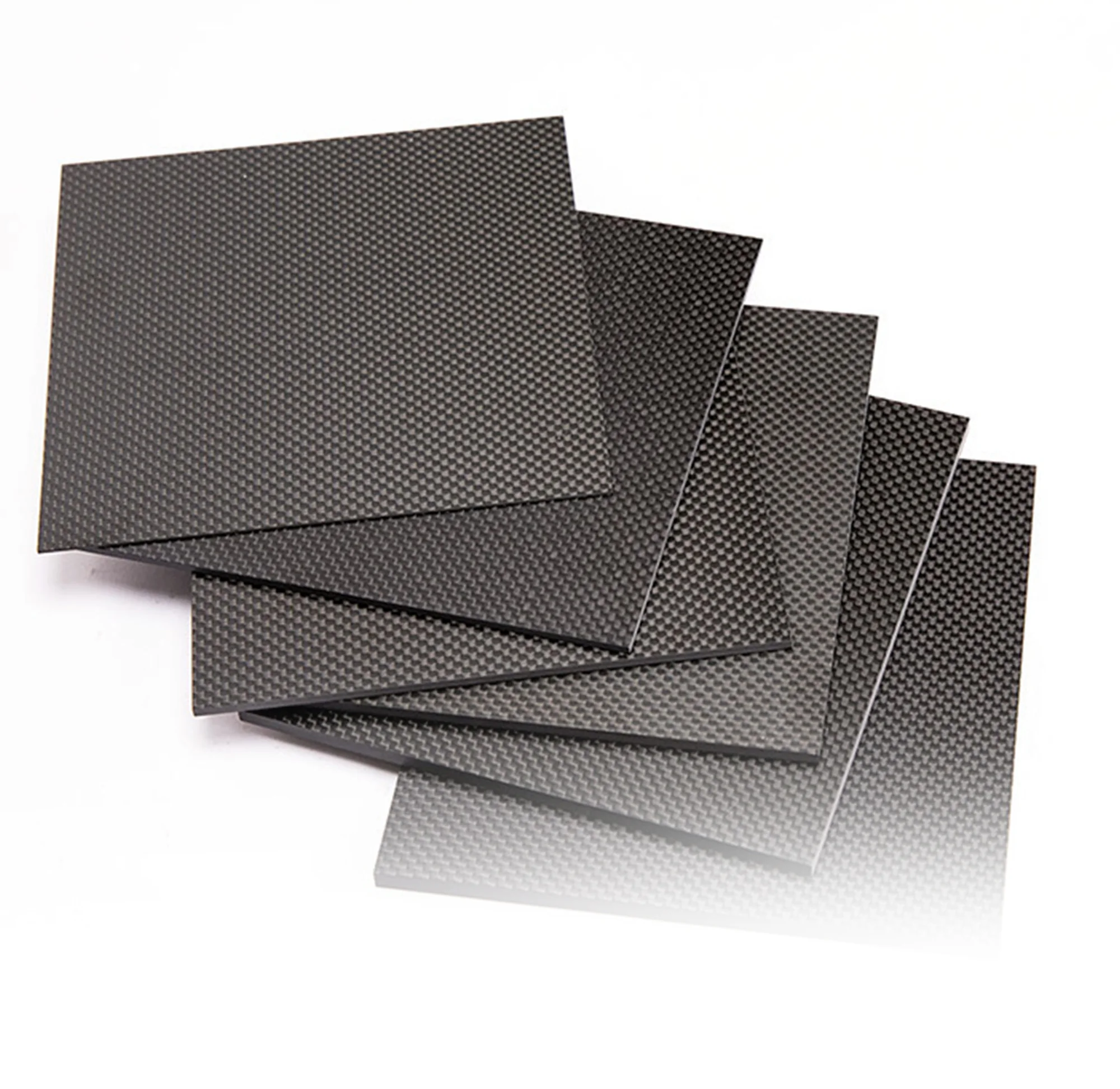
| Solid cured CFRP laminate | A stack of consolidated fiber-reinforced plies and matrix | Layup, thickness distribution, fiber orientation, edge and hole response |
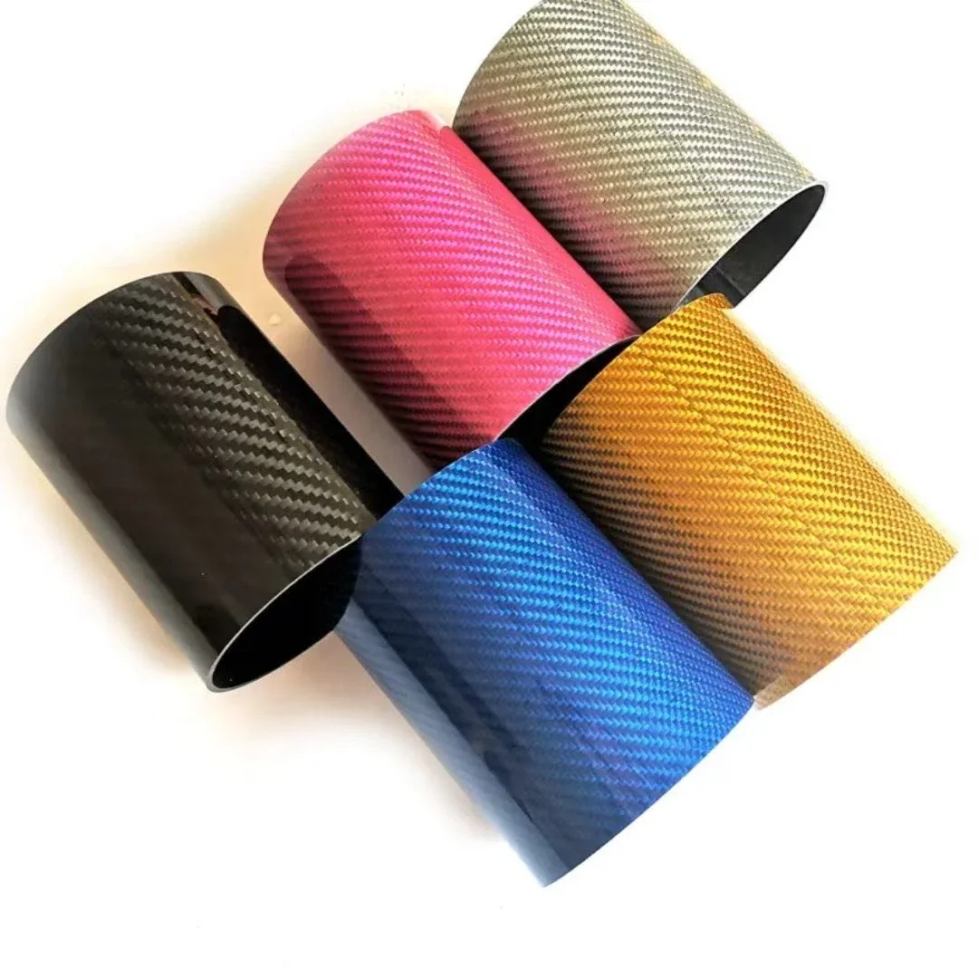
| Thin decorative carbon-fiber veneer | A thin finished skin intended primarily for visual covering | Substrate, attachment, handling and whether it carries any structural load |
| Carbon-skin sandwich panel | Two skins separated by a lower-density core | Individual skin thickness, core thickness/type, shear, bonding, inserts and edge closeouts |
In a solid laminate, fiber reinforcement and a cured matrix occupy the cross section, but the fiber angle and laminate schedule determine directional properties. In a sandwich panel, separating thin skins places material farther from the bending neutral axis; that can provide high bending stiffness at low mass, but creates core shear, local crushing, insert and skin-to-core bond design requirements.
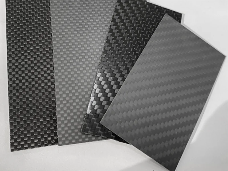
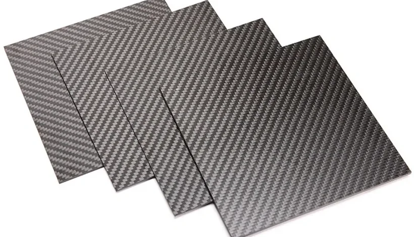
For example, a 5 mm overall sandwich panel is not equivalent to a 5 mm solid carbon-fiber laminate. The mass, cutting behavior and local fastener design can differ sharply. A photograph showing a woven outer ply says little about the hidden load-bearing stack; an engineer needs the verified construction, not just the visual weave.
Thickness affects bending stiffness—but not on its own
For a homogeneous, isotropic plate under an otherwise comparable bending condition, the bending rigidity depends approximately on the cube of thickness. In this idealized model, doubling thickness while keeping the same material and geometry yields about eight times the bending rigidity. This idealized mathematical trend explains why geometry can dominate bending response. It is a rigidity comparison, not an empirical CFRP strength or safe-load value.
It is not a promise that any carbon-fiber plate will deflect one-eighth as much when its thickness doubles. Real carbon-fiber laminates are direction-dependent. Adding plies may change the layup, resin content, processing defects, or material properties; shear deformation and boundary conditions may matter. Changing from a solid laminate to a sandwich panel invalidates a direct solid-plate comparison.
For a real laminated composite, engineers consider each ply’s stiffness, direction and distance from the mid-plane. Ply architecture governs the laminate’s bending stiffness in different directions. A sheet with a visually balanced 0°/90° weave may not behave the same as a sheet with hidden ±45° or direction-aligned unidirectional reinforcement.
Span and support are equally important. A long unsupported panel may deflect noticeably even when a small offcut of the same stock feels rigid in the hand. Where the panel is supported, whether edges are simply supported or clamped, and whether loads act at a point or across an area all affect measured deflection. Peer-reviewed flexural work examining specimen span shows why test geometry must accompany any quoted bending result.
Compare the actual engineering goals
Choose the design question before choosing the stock thickness. This prevents a lightweight panel problem from turning into an expensive grade substitution that does not address the load path.
| Design concern | More useful input than a nominal thickness alone | Follow-up verification |
|---|---|---|
| Excessive deflection | Unsupported span, load magnitude/location, allowable movement, edge support | Layup-aware bending analysis or representative load test |
| In-plane tensile or compressive loading | Fiber direction, plate width, net section, hole position | Direction-specific material data and joint design |
| Weight limit | Panel plan area, total construction, areal mass, inserts/coatings | Mass estimate for the complete part |
| Repeated loading or vibration | Load cycle, stiffness target, mounting details | Relevant fatigue/dynamic and joint qualification |
| A flat assembly surface | Final width/length, allowable bow, twist and thickness variation | Defined flatness and measurement conditions |
| Machined edges and holes | Kerf allowance, minimum edge distances, insert loads, finish | Tool/process-specific cut trial and inspection |
| Cosmetic cover | Finish, weave appearance, substrate and attachment | Surface approval and dimensional fit |
A thicker panel can reduce deflection but increases material mass and may shift loads into joints or edge features; compare the complete design rather than thickness alone. A different ply layout may improve directional stiffness without increasing thickness as much. A sandwich construction may offer an attractive stiffness-to-mass balance but introduce local edge and insert complexity. These are design tradeoffs, not universal material rankings.
Layup matters even when two sheets have the same thickness
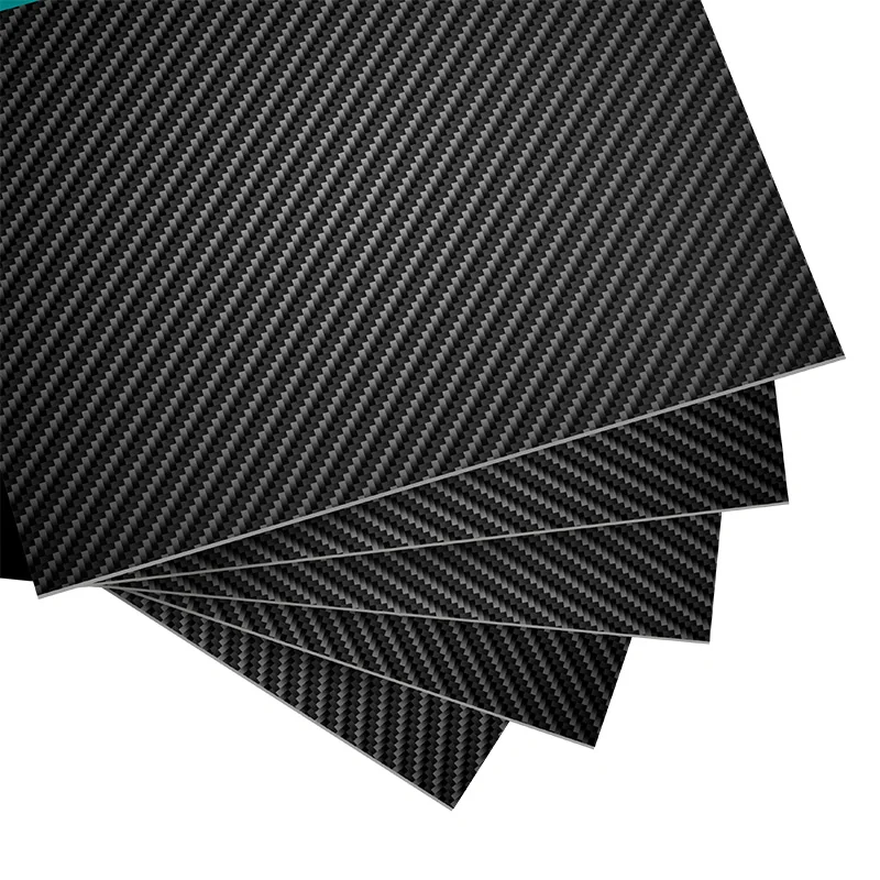
A carbon-fiber surface pattern is not the complete structural specification. Woven face layers can be chosen for finish and reinforcement in two directions. Other layers may be arranged to carry axial, transverse or shear loads.
For a beam-like component whose primary bending direction is known, orienting reinforcement along the relevant stress directions can change directional stiffness without assuming any universal grade upgrade. For a part carrying torsion, balanced angle plies may matter. Symmetry and ply order can also help manage unwanted bending–twisting coupling and manufacturing distortion.
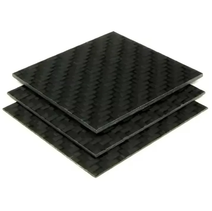
Published manufacturer examples show that sheet construction can vary with grade and listed thickness. These examples are evidence of those manufacturers’ own products only; they do not demonstrate which grades, stackups or thicknesses CFRPWorks presently offers.
For two independently supplied sheets both labeled “2 mm carbon fiber,” compare the cured ply schedule, resin, fiber orientation and measured property basis before treating them as interchangeable structural material. The quoted 2 mm is an illustrative catalog label, not a CFRPWorks offering. Do not infer identical performance from the same nominal gauge or visible weave.
Panel size is not the same as finished-part size
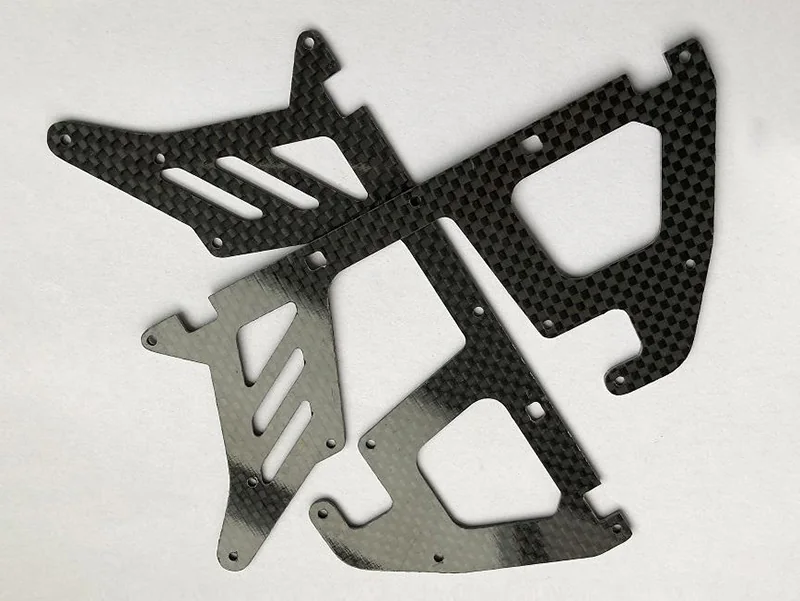
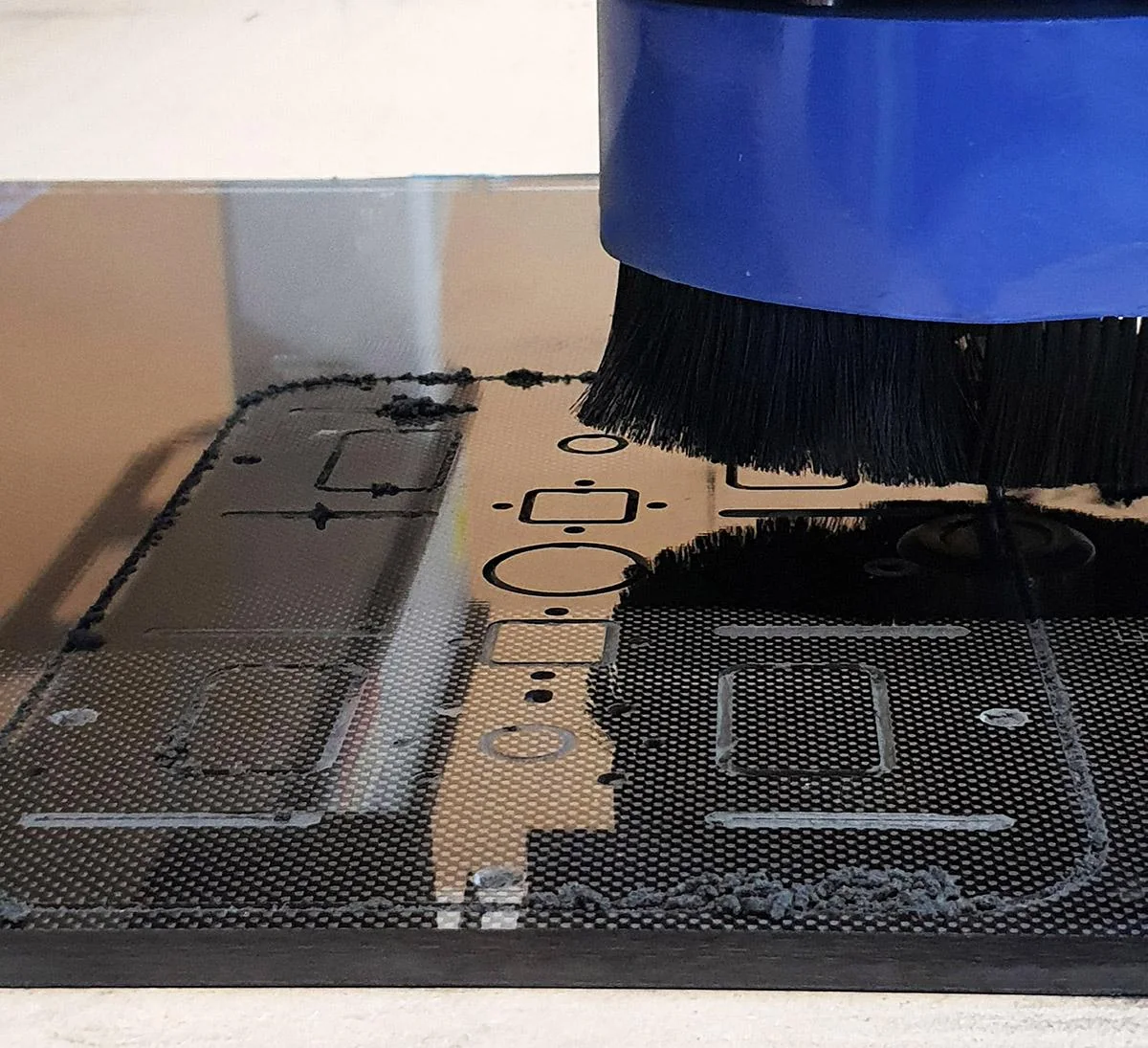
A “sheet size” may describe raw blank width/length, an edge-trimmed usable area or the final shape on the drawing; treating those as the same measurement can invalidate a nested cut plan. Those three values can differ. The cutter may need extra material for gripping or finishing; a part may require holes, countersinks, beveled edges or a non-rectangular profile.
For drawing-led fabrication, distinguish:
- Blank dimensions: the raw width and length before trimming.
- Finished dimensions: required cut outline and datum references.
- Thickness: nominal design target plus allowed measured range where applicable.
- Flatness: how much deviation is allowed, over what area and by which inspection method.
- Edge quality: visible or allowable fiber exposure, chipping, delamination and finishing requirements.
- Hole/insert features: size, location, edge distance and acceptance criteria.
- Surface requirement: matte/glossy, which faces are finished, and whether finishing changes thickness.
A vendor’s nominal gauge list is useful for preliminary procurement but does not establish the cured thickness distribution, panel flatness or production yield of another supplier. DragonPlate discusses the distinction between nominal and actual sheet thickness in its published measurement guidance. The exact allowable variation should be specified or agreed for the relevant item and process, not inferred from a generic product label.
How to verify thickness and stiffness claims
For a structural panel, the evidence should match the engineering decision. A nominal stock list helps with preliminary sourcing. A material datasheet may help evaluate grade or layup. A flexural coupon or part test may help establish response for a specific construction, specimen span and support arrangement.
Flexural test methods such as ASTM D790 are used to characterize suitable polymer and reinforced material specimens. Depending on the composite material, engineering acceptance basis and applicable standard, another method may be more appropriate. Instrument-maker guidance describes how test support span, specimen thickness and loading arrangement influence the result. A reported flexural modulus or strength belongs to a particular test method, specimen and span. It cannot automatically certify a larger perforated panel or an assembled structure under a different support condition.
When comparing a datasheet with a proposed panel, ask whether the published value represents the same resin, ply sequence, cure, thickness, fiber axis, conditioning and loading mode. For sandwich panels, include core shear and skin-bond behavior rather than using skin tensile data alone.
For a practical acceptance plan, define which evidence is needed at each stage:
- Material identification: reinforcement architecture, resin, layup or core/skin specification.
- Dimensional inspection: cured thickness measurement, location, variation and flatness.
- Representative bending assessment: applied loading, span, supports, direction and deflection.
- Feature inspection: finished edge, drilled holes, inserts, bonding surfaces and any localized damage.
- Part-level confirmation: only where the actual assembly or safety function demands it.
No single supplier’s nominal thickness chart can substitute for this sequence when a component is load-bearing.
A worked decision example without an invented load rating
Imagine an electronics enclosure needing a flat, visually finished carbon-fiber cover. A designer may first require precise fit, low mass and acceptable deflection between mounting screws. The initial specification should list the cover’s span, hole layout, environmental exposure and acceptable bow; it need not begin with a universal “best thickness.”
Now consider a fixture plate used in industrial equipment that carries a repeated transverse load and has fasteners near the edge. Its review should consider bending, bearing and fatigue, as well as the effect of holes and edge distances. A sheet that feels stiff as an unmachined rectangle may have different stiffness and local failure modes after mounting and cutouts; inspect the finished geometry.
For either case, use representative material data or a trial and check the actual drawing. If a trial fails a deflection target, revisit support, span, laminate architecture and thickness before assuming a higher bare-fiber modulus addresses the real structural issue.
What to include in a thickness-and-size inquiry
A useful technical inquiry provides the final drawing or CAD file with revision, overall dimensions, required measured thickness and tolerance objective, unsupported span, support arrangement, loading direction, deflection target, finish, cut details, holes/inserts, quantity, environmental conditions and whether mechanical verification is required.
If the buyer has not yet chosen a grade, it is reasonable to describe the selection as an engineering evaluation, not a confirmed product specification. The project may need to compare solid and sandwich construction, qualify the layup, or identify a manufacturing route before dimensions become final.
Frequently asked questions
Is a thicker carbon-fiber sheet always stronger?
Not without defining the property and load case. Greater section thickness can improve bending resistance, but tensile performance, local holes, ply orientation and defects require their own assessment. Nominal thickness is not a single strength rating.
Does doubling the thickness make it eight times stiffer?
An eightfold bending-rigidity trend follows an idealized cubic-thickness model for comparable homogeneous plates. It cannot be directly applied to a different CFRP layup, a sandwich design, different supports or every finished-part deflection.
Why do two sheets of equal thickness bend differently?
Different fiber alignment, resin, stacking sequence, voids and core constructions produce different directional stiffness. Span and how the sheet is supported can add another substantial difference.
Does the listed sheet thickness include a tolerance?
A nominal gauge is not automatically an exact measurement. Request the appropriate cured-thickness range, measurement method and flatness requirement from the actual supplier or establish them in the purchase specification.
What size information is needed for a custom-cut panel?
Provide blank versus finished dimensions, CAD geometry, hole and insert details, thickness/tolerance objective, flatness and surface requirements, use-case load and needed inspection. Confirm cutting allowance and the available stock separately.
Next step: match dimensions to the right product decision
View Related Product / Capability: Use the Carbon Fiber Sheets product family to evaluate the physical sheet format, or describe exact finished dimensions and machining requirements for a custom-cut sheet inquiry. Verify the proposed construction, usable blank size, actual thickness range and fabrication/inspection requirements with CFRPWorks for the specific drawing; this guide does not establish live stock or a guaranteed tolerance.
Related technical guides: Carbon Fiber Strength & Properties · How to Cut Carbon Fiber.
References
- DragonPlate — Gauging the Thickness of Carbon Fiber Sheets
- Instron — Guide to ASTM D790 Flexural Testing
- Easy Composites — High-Strength Carbon Fibre Sheet Product Information
- Kumair — Carbon Fiber Laminate Structure
- De Gruyter — Span-Length Effect on Composite Laminate Flexure
Carbon Fiber Sheets · Custom-Cut Carbon Fiber Sheets · More Technical Guides