Source context: Easy Composites — Mechanical Properties of Forged Carbon Fibre.
Forged carbon fiber and conventional woven carbon fiber are both types of carbon-fiber-reinforced composite. The main difference is how the reinforcement is arranged. A product called forged carbon typically contains chopped or discontinuous carbon-fiber pieces consolidated with a polymer resin, commonly in a compression mold. A conventional woven or unidirectional laminate contains long, continuous fibers placed in selected orientations before consolidation.
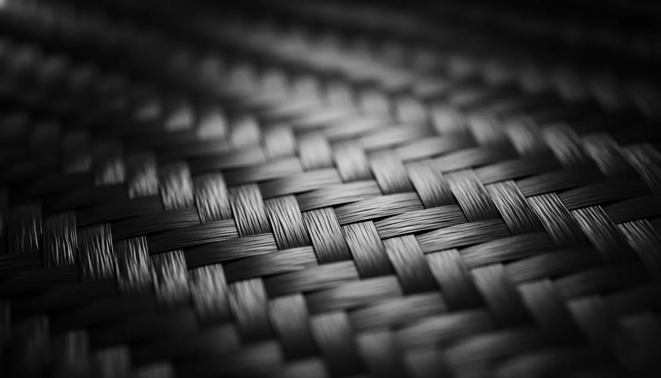
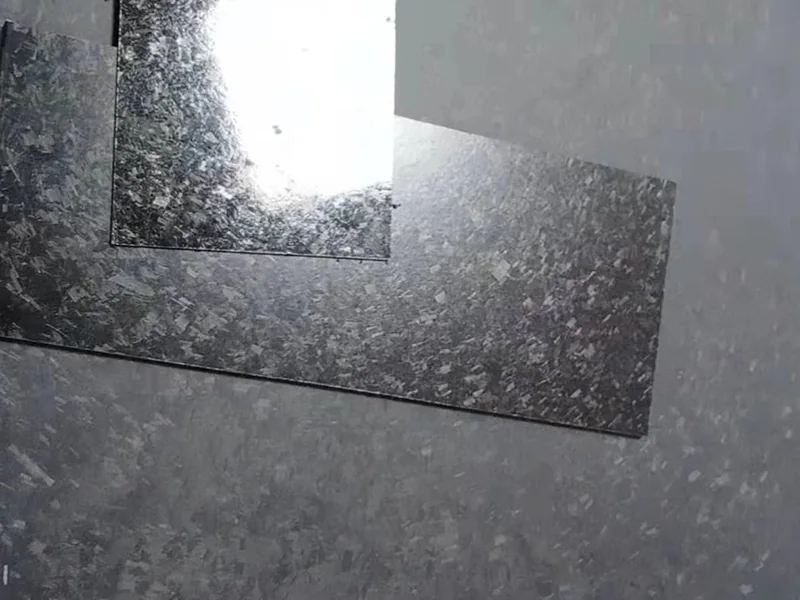
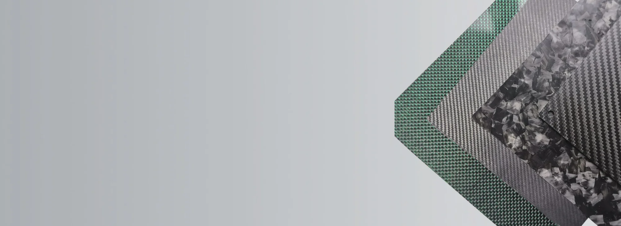
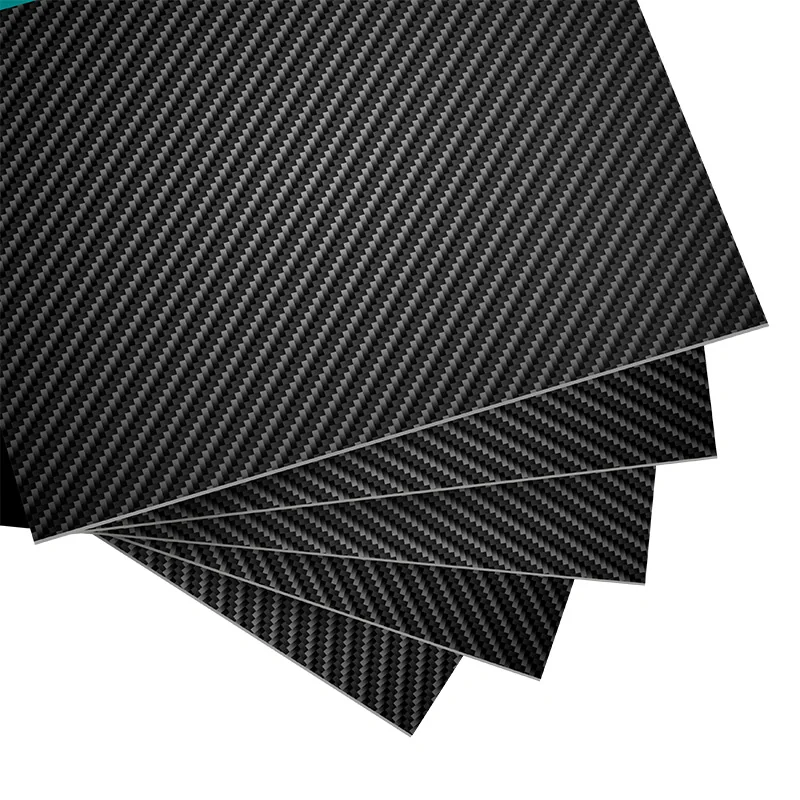
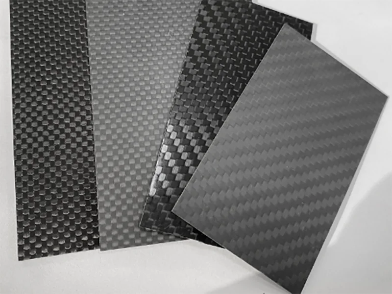
The visible surfaces can look very different: chopped charges often reveal an irregular, marble-like pattern, while exposed woven plies reveal a repeated twill or plain-weave grid. Painted, coated or hidden structures may show neither. But visual appearance alone does not establish strength, stiffness, weight, manufacturing quality, or suitability for a particular component.
The engineering decision is: Which specific fiber architecture, resin system, part geometry and validation approach fits the required load case, finish and production quantity?
Quick comparison: chopped versus continuous reinforcement
| Decision factor | “Forged” chopped-fiber composite | Woven or unidirectional continuous-fiber laminate |
|---|---|---|
| Reinforcement | Chopped tow, prepreg chips or another discontinuous-fiber molding compound | Continuous woven fabric, unidirectional tape or layered prepreg |
| Surface appearance | Often a mottled, irregular pattern when fibers remain visible | Often regular weave or aligned fibers when a layer is visible |
| Fiber placement | Charge placement and molding flow influence local orientation | Ply angle and fiber direction can be specified deliberately |
| Shape creation | Compression molds may form ribs, bosses and complex thickness transitions | Laid-up or infused fabric can form shells, sheets, tubes and targeted load paths |
| Directional stiffness | Depends on local fiber distribution, resin and molded structure | Can be tailored along defined load directions with continuous plies |
| Tooling and repetition | Matched molds, charge control and process qualification may require substantial upfront work | Layup, molding, bagging and trimming requirements depend on process and geometry |
| Cost basis | Material charge, molding cycle, tooling, scrap, secondary steps and production volume | Fabric/prepreg, cutting and layup labor, cure, trim, joints, inspection and volume |
| Valid design evidence | Test the actual molded compound, fiber distribution and critical features | Test the actual cured stacking schedule, directions and final component features |
Neither column describes a single material specification. Chopped molding compounds vary in fiber length distribution, matrix, material charge and reinforcement volume. A part that contains 12 mm chopped tow cannot automatically inherit data from a differently sized prepreg chip system. “Conventional carbon fiber” can mean several very different continuous reinforcement systems. A meaningful comparison names both actual constructions and the test basis.
What does “forged carbon fiber” mean?
The word forged is a commercial description, not a metalworking process, certification class or proof of a specific carbon-fiber grade. Many products with that label are made from chopped carbon fibers or chopped prepreg pieces distributed in resin and consolidated into a shape. Compression molding is a common route, but the label alone does not guarantee any specific tool, resin, fiber length, curing system or quality level.
One possible compression-molding process begins with a measured charge: an identified mass and arrangement of reinforcement and matrix material placed inside a suitably designed mold. Under an appropriate process, pressure and temperature consolidate the material into the mold’s cavity. Short fibers can move into complex features that a continuous textile might resist without cutting or repositioning.
The technical literature describes several distinct discontinuous material forms, including chopped prepreg chips, sheet molding compound and bulk molding compound. Their properties differ. A chopped-fiber injection-molded plastic or a 3D-printed short-fiber filament also uses discontinuous reinforcement; its fiber retention, orientation and porosity can differ markedly from compression-molded chopped prepreg. Its test results should not be borrowed to rate a forged-carbon part.
By contrast, a continuous-fiber laminate starts with fabric or tape whose reinforcement stays continuous across all or part of the layup. A designer can specify 0°, 90° and angle plies to align reinforcement with the anticipated force directions. Continuous fibers are not a guarantee of good design: wrinkles, cuts, incorrect stacking, voids, joints and poor cure can compromise the final structure.
Appearance: marbled versus woven is not a performance test
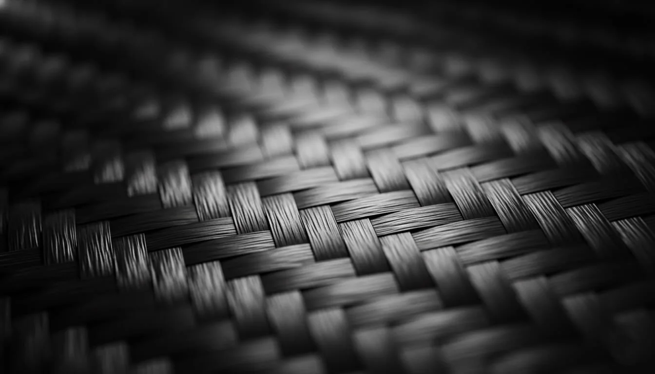
Forged carbon’s visible irregularity comes from chopped fiber bundles showing at different orientations within the surface. Regular woven carbon reveals the ordered pattern of cloth. Both can be polished, coated, painted or covered, which means a photograph may not show the entire architecture.
The term “forged” is often used to describe the visual effect of irregular fragments, but a cosmetic pattern is not a specification for an unseen structural stack. A clear-coated decorative panel may be selected primarily for its finish. A load-bearing mount needs data about the resin, reinforcement, section design and expected loading.
For an appearance-led part, obtain a representative finish sample and agree on surface consistency, exposed fibers, edge treatment and inspection. For a structural part, obtain a material and test specification independently of the visual finish. Do not assume that two marbled parts made by different processes perform alike.
Fiber continuity and load direction
Continuous fibers can transmit tensile loads along their length over the area they reinforce. This makes a well-designed unidirectional or multidirectional continuous laminate useful for long and predictable load paths. Its strength and stiffness are often anisotropic: the result changes with angle, laminate architecture, resin and cure.
Chopped fibers terminate inside the part. Loads transfer into and out of each short segment through the resin matrix and fiber–matrix interfaces. Local reinforcement continuity is therefore unlike a full-length ply crossing a long tensile load path. Distribution may produce useful behavior in several directions, but a random-looking surface does not prove isotropic properties. During molding, compound flow, local wall thickness, ribs and corners can reorient reinforcement. Local resin-rich zones, fiber accumulation or voids may alter the result.
This difference does not automatically rule out a chopped compound in structural use: its part geometry, material system and validated load cases determine suitability. The TenCate/Toray technical paper on chopped prepregs discusses molded structural components and shows that comparisons can change when holes and other real component features are introduced. Those data belong to the documented compound, process and test geometry; they are not certified figures for every product marketed as forged carbon.
For an important part, ask for strength and modulus in relevant loading directions, plus the actual joint, hole, fatigue or impact evidence required by its application. Tensile modulus is stiffness, not the same as ultimate tensile strength.
Shape complexity can matter more than the surface label
Imagine a small cosmetic trim piece with tight contours, a shallow rib and a recessed screw location. A molded chopped-fiber approach may be attractive because the molding charge can form several details together. That hypothesis still requires a qualified mold, charge arrangement, acceptable edge quality and repeatable finish.
Now imagine a long, thin panel that carries tension predominantly along one axis. A continuous-fiber layup can place reinforcement along that direction, potentially making a different use of material. Yet it might require more complex draping, trimming or joining if the actual shape has deep ribs or corners.
Neither example is a supplier’s finished-part performance claim. They show why geometry, net section, support and production quantity should be assessed together rather than selecting by a material nickname or the surface color.
Which option is stronger?
There is no defensible universal “forged carbon is X% stronger” or “woven carbon is X% stronger” answer. Strength comparisons should identify material grade and fiber length, resin system, fiber fraction, tested direction, specimen geometry, thickness, conditioning, number of samples and failure mode.
A continuous laminate optimized for a single primary tension direction can use long, aligned reinforcement efficiently. A chopped compound may show different sensitivity to a notch or hole. A compression-molded part may gain structural rigidity from molded ribs or thicker local sections, even when its constituent tensile properties are not the same as a flat continuous coupon.
Easy Composites has published an illustrative mechanical investigation of forged-style components. It is useful because it identifies a tested design, not because one experiment proves a category-wide ranking. The chopped-prepreg technical paper published under the TenCate/Toray materials archive likewise describes the effect of component features and molding strategies under its specific conditions.
For critical designs, compare at three levels:
- Material evidence: documented resin, fibers, charge or ply schedule, and coupon results in the relevant direction.
- Feature evidence: holes, fasteners, ribs, thickness changes, impact points and joining regions.
- Component evidence: actual geometry, process variation, load spectrum and acceptance tests.
Bare-fiber supplier data, an unnotched coupon, and a polished presentation sample answer different questions; none can silently substitute for the required finished-part evidence.
Is forged carbon more economical?
It can be economical for certain complex shapes and repeat volumes, but neither lower price nor faster delivery is inherent in the label.
The total comparison includes mold design and tooling investment, material form, labor for cutting and layup, charge preparation, press time and curing, scrap, trimming, finishing, inserts, inspection, rejected parts and assembly steps. A complex continuous part may need bonded pieces; a well-designed molding compound part may integrate features. Conversely, a simple low-volume panel might not justify production tooling for a compression-molded alternative.
The commercial question is therefore cost per accepted finished part at a specified volume, not simply the price of a bag of chopped tow against a piece of woven cloth. Prototype tooling, development iterations, scrap and repeat-order volume can reverse an earlier unit-cost comparison. Analyze both upfront qualification spend and per-accepted-part cost.
Keep mechanical qualification and appearance acceptance in the cost calculation. Savings that depend on eliminating tests or ignoring defective edges are not a valid material-selection argument.
A practical selection framework for engineering buyers
Use these questions in this order:
- What is the component’s job? Cosmetic cover, stiffness-critical beam, reinforced housing or part with molded features?
- Where do loads enter and leave? Known primary axis, multidirectional forces, bolt holes, inserts and bonded joints?
- Which shape is needed? Thin continuous panel, deep 3D form, ribs or varying section thickness?
- What surface is acceptable? Visible regular weave, variable marbling, painted finish or unimportant interior appearance?
- What quantities are realistic? Prototype, tooling qualification, occasional reorder or repeat volume?
- What evidence must accompany the part? Material identity, process controls, dimensional inspection, tested performance or customer approval?
A material label should become a drawing-level requirement with the relevant load direction, surface, geometry, material verification and acceptance tests explicitly identified. If the chosen concept uses chopped reinforcement, clarify the matrix and chip system, molding method and sample verification. If continuous reinforcement is chosen, clarify the ply orientations, cure, machining and reinforcement around attachments. Hybrid constructions may be considered, but they require their own engineering and process evidence.
Frequently asked questions
Is forged carbon fiber real carbon fiber?
Yes. The reinforcement can be genuine carbon fiber, but it is usually used as chopped or discontinuous pieces in a cured composite. The marketing term does not describe one universal material specification.
Does forged carbon contain a woven layer?
Some components may combine chopped and continuous reinforcement, but the visible marbled pattern does not prove that an internal woven layer exists. Request a documented material construction rather than inferring the hidden stack from a photo.
Is forged carbon always less strong than woven carbon?
No universal conclusion is valid because the test specimen, reinforcement direction and final component geometry may be different. A load-aligned continuous laminate, a chopped-prepreg molded sample, and a part with real holes or ribs are different test cases. Compare the actual material and finished design, including the direction and failure mode.
Can random chopped fibers make a part equally strong in every direction?
Not automatically. Molding flow, charge location, fiber length and part geometry can create orientation and local differences. “Random” is not a substitute for measured directional properties.
Which one costs less for a custom component?
It depends on geometry, volume, material and process, tooling, inspection and assembly. For a reliable quote comparison, describe the same accepted part, finish and qualification conditions for both options.
Compare options using your drawing
Compare Options / Request Quote: Begin with the required part geometry, appearance, load case, fastening approach, expected quantity and acceptance evidence. A CFRPWorks inquiry can be based on a clear requirements brief for comparison and supplier qualification. It does not establish that a forged-carbon grade or compression-molding process is currently available; confirm actual capabilities, materials and terms for the specific project.
Related technical guides: Types of Carbon Fiber · Carbon Fiber Strength & Properties · Carbon Fiber Cost Factors.
References
- Easy Composites — Mechanical Properties of Forged Carbon Fibre
- TenCate/Toray Advanced Composites — Chopped Prepregs Technical Paper
- International Journal of Lightweight Materials and Manufacture — Manufacturing Methods and Mechanical Properties
Related CFRPWorks resources: Carbon fiber resources · Custom carbon fiber parts · Custom carbon fiber manufacturing.