
APPLICATIONS / DRONE & UAV ENGINEERING
Carbon Fiber Drone Applications: Engineer for the Mission
A carbon fiber drone is an aircraft system; the appearance of its frame material says little about whether the design meets its mission requirements. For an unmanned aircraft, a composite structure has to carry flight, landing and handling loads while protecting the alignment of motors, sensors, payloads and control hardware. Carbon-fiber reinforced polymer (CFRP) can be considered when weight and stiffness are important, but useful performance depends on the completed laminate, geometry, joints and operating conditions. A lightweight panel that satisfies one mission may be inappropriate for another.
This page examines UAV application fit and specification rather than selling a particular frame or kit. If the purchasing task is a specific physical frame, plate or drawing-controlled component, use the separate product-family route rather than treating this application discussion as a frame specification.
Material / geometry illustration only. No photograph on this page proves UAV airworthiness or a certified CFRPWorks aircraft.
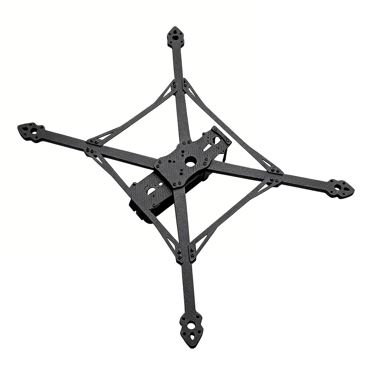
Carbon-fiber structural profiles • material reference, not a flight-approved UAV assembly.
01 / MISSION FIT
Start with the mission, not the material label
01
Multirotor imaging or inspection
Design question. What payload alignment and sensor stability are needed in hover, maneuvering and landing?
Evidence to establish. Loaded mass and balance, motor attachment loads, vibration limits and interface drawings.
02
FPV or other repeatedly handled multirotors
Design question. How should repeated handling, impacts and field replacement affect arm and connector requirements?
Evidence to establish. Assembly loads, crash/inspection criteria, replacement strategy and durability acceptance.
03
Mapping or endurance-oriented UAVs
Design question. Does the installed mass difference justify any trade-off in stiffness, assembly time or field repair?
Evidence to establish. Mission mass budget, complete assembly comparison, expected flight environment and joining details.
04
Fixed-wing or VTOL airframes
Design question. Which operating modes and interface loads govern wings, booms or payload-support structures?
Evidence to establish. Configuration-specific load cases, laminate concept and responsible design/approval authority.
Engineering contexts are not evidence of completed CFRPWorks aircraft programs; loaded performance must be verified for the actual system.
These are common engineering contexts, not a list of completed CFRPWorks aircraft programs. Flight endurance, payload and handling cannot be predicted from the word carbon fiber or transferred from a third-party drone design.
02 / STRUCTURAL DECISIONS
Where the structural trade-offs appear
Aircraft-level performance depends on the assembled geometry, interfaces and operating conditions—not the material label.
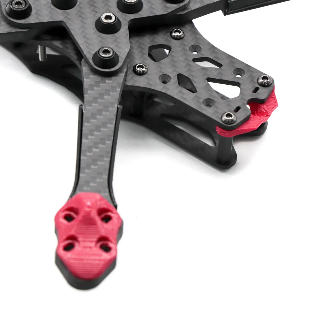
Woven reinforcement example: surface weave does not reveal the full laminate ply stack.
01
Trade-off 1
Mass versus installed stiffness. Density alone is not a UAV-level performance metric. Compare the finished structure with its inserts, bolts, joints, protective coatings and replacement provisions. Ask where stiffness must be retained under bending or torsion. A nominally lighter plate can lose its advantage once the supporting assembly and its real operating conditions are included.
02
Trade-off 2
Fiber direction and load path. The properties of a CFRP laminate are direction-dependent. A design should state where motor-arm bending, center-plate torsion, landing loads and localized bearing forces enter the structure. Visible weave does not reveal the complete ply stack, fiber orientations or design allowables.
03
Trade-off 3
Vibration and sensor behavior. Rotor-induced excitation can make flexibility or resonance important to the application. Define permissible displacement or vibration at each relevant sensor and motor interface before requesting a design review or representative test. CFRP is not a universal vibration isolator; the assembled structure, excitation and damping treatment govern behavior.
04
Trade-off 4
Joints, fasteners and damage. Hole geometry, fastener spacing, adhesives or inserts can influence local strength and serviceability. Contact with dissimilar metals may call for a compatible interface design. After an abnormal landing, inspection and replacement criteria should reflect the possibility of damage below a visually intact surface.
05
Trade-off 5
Environment and maintenance. State the temperature range, moisture or UV exposure, transport conditions and access requirements for field repair. Environmental and fatigue acceptance applies to the selected cured material and joined assembly, not to the name of the reinforcement alone.
03 / REQUIREMENTS BRIEF
Translate the UAV concept into a controlled component request
A useful engineering inquiry separates what the UAV must do from which physical part should be supplied.
Mission and development stage
Airframe type, flight/use scenarios, prototype versus released drawing.
Geometry and interfaces
Overall envelope, mount locations, datum scheme, bolt patterns, mating materials, clearance and service access.
Load and dynamic conditions
Expected flight and landing loads, payload, vibration sources, duty cycle and handling events when known.
Material decisions
Existing laminate/resin requirements or the variables still open for feasibility review.
Acceptance criteria
Fit-critical features, visual/dimensional inspection, required material records and application-specific tests or approvals.
Order context
Sample quantity, prospective production volume and design revision; do not treat a forecast as a firm quantity.
Mark unknown parameters as open for engineering review; do not fill blanks with assumed mass, ply schedule, tolerance or load capacity. For safety-sensitive use, the project owner should define the required approval process and supporting evidence. Neither a general application description nor a supplier product photograph substitutes for this approval.
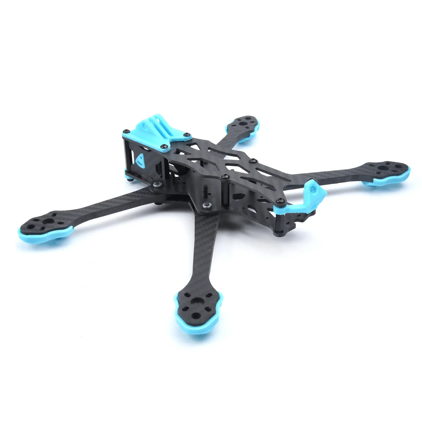
Composite sheet geometry • example only; thickness, ply schedule and tolerances are project-specific.
04 / SELECT YOUR NEXT ROUTE
Choose the next page by your buying task
If the geometry and interface requirements are already defined for a physical drone frame, continue to the dedicated carbon-fiber drone frame product family to review drawing and configuration questions. If the need is an individual mount, bracket or other finished drawing-led part, use the custom carbon-fiber parts product family. The broader Applications overview is useful if a project spans multiple industries. An RFQ should carry the mission, current drawing revision and verification requirements. Confirm an appropriate receiving and confidentiality arrangement before sending controlled design files.
Physical drone-frame sourcing
For a specified UAV frame, plate or drawing-controlled component, follow the physical product-family route.
Explore drone frames →Made-to-drawing individual parts
For individual mounts, brackets or finished components, use the custom parts buying route.
Explore custom parts →Broader application discovery
Review other industry paths in the Applications overview before choosing a physical product.
Applications overview →05 / ENGINEERING FAQ
Drone and UAV application FAQs
Does a carbon fiber drone always achieve a longer flight time?
No. Battery, propulsion, aerodynamics, payload and the installed structural mass all matter. Any endurance improvement must be evaluated on the actual completed UAV under comparable conditions.
Is a carbon fiber arm automatically stiff enough for a particular motor?
No. Arm section, laminate orientation, span, joint design and loading define the result. Specify the motor interface, loading and required deflection or vibration behavior before deciding whether a proposed construction is suitable.
Can a supplier's carbon-fiber frame photograph demonstrate airworthiness?
No. A photograph can show geometry or appearance, not documented structural margins, inspection results, traceability or aviation approval for a specific use.
What is different about a UAV application page and a drone-frame product page?
The application page helps determine functional and verification requirements for the UAV mission. The product page addresses the physical frame family, drawings, fit and quotation inputs. One does not replace the other.
What if the project is still at the concept stage?
Start with the mission, mass budget, rough geometry, mounts and unknown load cases. Ask for feasibility questions to be identified before treating a conceptual configuration as production-ready.
DRAWING-LED INQUIRY
Discuss application requirements
Discuss Application Requirements. Prepare a current drawing or concept sketch, the intended service conditions and measurable acceptance questions. Use a verified contact channel for any confidential design package; no file-transfer or response-time promise is made here.
06 / REFERENCES
Further reading
CompositesWorld — Drones: Composite UAVs Take Flight — third-party examples of composite UAV uses, not this brand's project history.
Frontiers in Mechanical Engineering — UAV Airframe Structural Analysis — study-specific analysis; its numeric findings do not establish results for other designs.
External material is technical context only. Neither referenced study validates a CFRPWorks part nor authorizes a flight-performance claim.