By CFRPWorks
Source context: Toray TORAYCA™ T300 technical data, Kaiser Aluminum 6061 and 7075 technical data, FAA composite-structure guidance, NASA technical research, and ORNL manufacturing-cost research. Full reader-facing sources are listed in References.
Carbon fiber and aluminum are often compared as if one material simply replaces the other. That framing is too simple for engineering work.
Aluminum is a metal with comparatively predictable, nearly isotropic behavior. Carbon-fiber-reinforced polymer (CFRP) is a designed laminate whose stiffness and strength depend on fiber direction, stacking sequence, resin system, fiber volume, manufacturing quality, joints, holes and the actual load path. The result is that CFRP can deliver a large stiffness-to-weight advantage in the right structure, while aluminum can remain the better choice when impact, heat spreading, local bearing loads, easy modification, welding, low tooling cost or multidirectional loading dominate.
The useful question is therefore not “Is carbon fiber better than aluminum?” It is:
Can this part be redesigned to exploit CFRP’s directional specific stiffness enough to justify the extra design, manufacturing and inspection complexity?
Quick answer: when each material usually has the advantage
| Design question | CFRP tends to have the advantage when… | Aluminum tends to have the advantage when… |
|---|---|---|
| Weight | mass reduction has high system value | mass is secondary to cost or simplicity |
| Stiffness per unit mass | loads are known and fibers can follow them | loading is strongly multidirectional or geometry is not optimized for composites |
| Static strength | laminate, joints and failure modes are designed and verified | ductile behavior and familiar metal allowables simplify the design |
| Impact / visible damage | impact threats can be controlled and inspected | denting, local abuse or easy visual inspection matter |
| Holes / threads / bearing loads | inserts and local reinforcement are acceptable | direct tapping, bolting and concentrated bearing loads dominate |
| Thermal management | low expansion or dimensional stability matters | heat spreading and high thermal conductivity matter |
| Manufacturing | integrated geometry and repeatable composite processing justify tooling | low-volume CNC, welding or late design changes matter |
| Service / repair | inspection and composite repair capability are available | field modification and conventional metal repair are priorities |
That table is only a screening tool. Final material selection still depends on the geometry, loads, environment, production route and acceptance evidence for the actual part.
Start with the right comparison: finished laminate versus aluminum alloy
One of the most common carbon-fiber comparison errors is to put bare fiber properties beside the properties of a finished aluminum alloy.
Toray lists T300 carbon fiber at approximately 230 GPa tensile modulus, 3,530 MPa tensile strength and 1.76 g/cm³ density. The same Toray data sheet also publishes representative composite properties for a T300/epoxy system normalized to 60% fiber volume: approximately 140 GPa tensile modulus and 1,820 MPa tensile strength in the tested fiber direction.
Those numbers illustrate an important rule: the fiber is not the finished part.
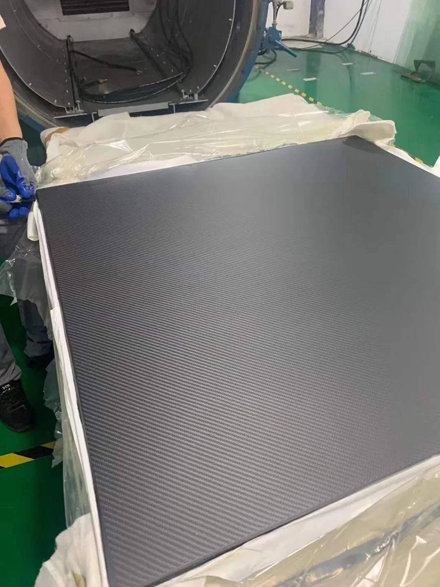
A cured laminate adds resin, interfaces, transverse directions and process effects. A real component adds holes, edges, thickness transitions, bonded regions, inserts and load-introduction points. A quasi-isotropic laminate deliberately gives up some peak 0° performance to carry loads in several directions.
For aluminum, the alloy and temper also matter. 6061-T6 and 7075-T6 are not interchangeable. 7075-T6 is substantially stronger than 6061-T6, but its elastic modulus is only slightly higher. That means switching from 6061 to 7075 can increase allowable stress without producing a comparable increase in elastic stiffness.
If your current part is deflection-limited rather than strength-limited, that distinction matters.
Weight: CFRP starts with a density advantage, but part weight is not a density calculation
Kaiser lists 6061 aluminum at about 2.70 g/cm³. 7075 is about 2.80 g/cm³. Representative carbon/epoxy laminates are commonly around the mid-1.5 g/cm³ range, depending on fiber, resin and fiber volume.
At equal external volume, CFRP therefore starts substantially lighter.
But equal volume is rarely the engineering question. The real comparison is usually one of these:
- equal maximum deflection;
- equal buckling margin;
- equal axial or bending load;
- equal fatigue or damage-tolerance requirement;
- equal packaging envelope;
- equal joint capability;
- equal functional life.
A flat CFRP plate with the same length, width and thickness as an aluminum plate may be lighter, but it may not have the same bending stiffness, impact behavior, hole performance or boundary conditions. Conversely, a laminate designed around the actual load path may achieve a larger weight reduction than density alone suggests.
That is why specific stiffness—modulus divided by density—is often more useful than density by itself for weight-sensitive structural screening.
Stiffness: specific stiffness is where CFRP can become compelling
Kaiser’s 6061 data show a modulus of elasticity around 68–69 GPa. Kaiser’s 7075 data are around 71 GPa. Their densities are both close to 2.7–2.8 g/cm³, so their specific stiffness is similar.
A representative 0° T300/epoxy laminate from the Toray data can have an axial modulus around 140 GPa at much lower density. On a simple modulus-to-density basis, that produces a much higher axial specific stiffness than either aluminum alloy.
But the word axial is doing important work.
CFRP is anisotropic. A unidirectional laminate is efficient along the fibers and much less capable in other directions. A real laminate may use 0°, ±45° and 90° plies to carry tension, compression, shear and transverse loads. Each added direction makes the structure more balanced, but it also changes the effective stiffness compared with the ideal 0° value.
For a real part, ask:
- What load direction actually controls deflection?
- Is the part dominated by bending, torsion, axial load, buckling or local joint deformation?
- Can fiber directions be aligned with the important loads?
- Does the laminate need quasi-isotropic behavior?
- Are holes, inserts or concentrated loads controlling the response?
- Is the current aluminum geometry still appropriate, or should the CFRP geometry be redesigned?
A carbon-fiber replacement is most effective when the geometry and laminate are designed together, rather than when a metal drawing is copied in composite material.
For more background on why a single headline strength or modulus value is not enough, see Carbon Fiber Strength: What It Means for a Real Composite Part.
Strength: do not confuse high tensile values with universal load capacity
Kaiser’s representative T6 values show the difference between common aluminum choices:
- 6061-T6: about 276 MPa yield strength and 310 MPa ultimate tensile strength;
- 7075-T6: about 503 MPa yield strength and 572 MPa ultimate tensile strength.
Those are bulk alloy properties for specified product forms and tempers.
CFRP needs a different design language. It does not have one metal-like yield strength that defines the whole laminate. Relevant failure modes can include:
- fiber tension failure;
- fiber compression or kinking;
- matrix cracking;
- interlaminar delamination;
- in-plane shear failure;
- open-hole tension or compression failure;
- bearing failure around a fastener;
- net-section fracture;
- bonded-joint or insert failure.
A 0° tensile coupon can therefore look exceptional while a poorly designed hole, insert or off-axis load controls the real component.
The practical rule is simple: compare the property that governs the actual part. If deflection controls, compare structural stiffness. If a bolted joint controls, compare bearing and bypass behavior. If accidental impact controls, compare residual strength after the relevant damage. If the part is a thin panel, buckling may matter more than smooth-coupon tensile strength.
Impact and damage tolerance: aluminum dents; composites can hide damage
Aluminum often provides visible evidence of local overload through denting or permanent deformation. CFRP can respond differently. Matrix cracks and delamination may extend beyond the visible surface mark, and the residual strength of a composite structure can depend strongly on laminate design and impact severity.
FAA AC 20-107B treats impact, inspectability, laminate details, joints and damage tolerance as important design considerations for composite aircraft structure. The guidance also distinguishes detectable and barely visible damage and emphasizes that composite structural substantiation depends on the actual design and test evidence.
That does not mean aluminum is automatically safer or CFRP is automatically fragile. Aluminum can fatigue and crack; CFRP can be designed with strong damage tolerance. The point is that their failure and inspection models are different.
When impact matters, the comparison should include:
- likely impact energy and contact shape;
- allowable visible damage;
- hidden-damage inspection method;
- residual strength after impact;
- replacement versus repair strategy;
- safety factor and structural redundancy.
If those requirements are not defined, “carbon fiber is stronger” and “aluminum is tougher” are both incomplete statements.
Holes, threads and joints often decide whether CFRP is practical
Metal parts are convenient around local load introduction. Aluminum can be drilled, reamed, tapped and clamped with familiar processes. A threaded hole in a sufficiently thick aluminum feature can be structurally straightforward.
CFRP behaves differently around concentrated loads. Fastener holes can introduce bearing stress, bypass stress, fiber breakage, matrix cracking and delamination. Threads are commonly handled with bonded or molded inserts rather than by treating the laminate like a block of metal.
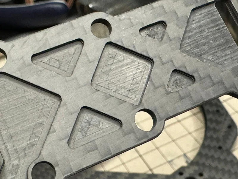
Composite joints may require:
- larger edge distances;
- local ply build-up;
- additional ±45° reinforcement;
- bonded inserts or metallic hard points;
- controlled drilling and hole quality;
- careful clamp-up;
- bearing, pull-through or net-tension verification;
- electrical isolation when carbon and aluminum are joined.
FAA guidance specifically notes the need to address both galvanic corrosion and the possibility of delamination or fiber damage during fastener installation.
This is one reason a part with excellent theoretical CFRP weight savings can lose some of that benefit after inserts, local reinforcement and joint hardware are added.
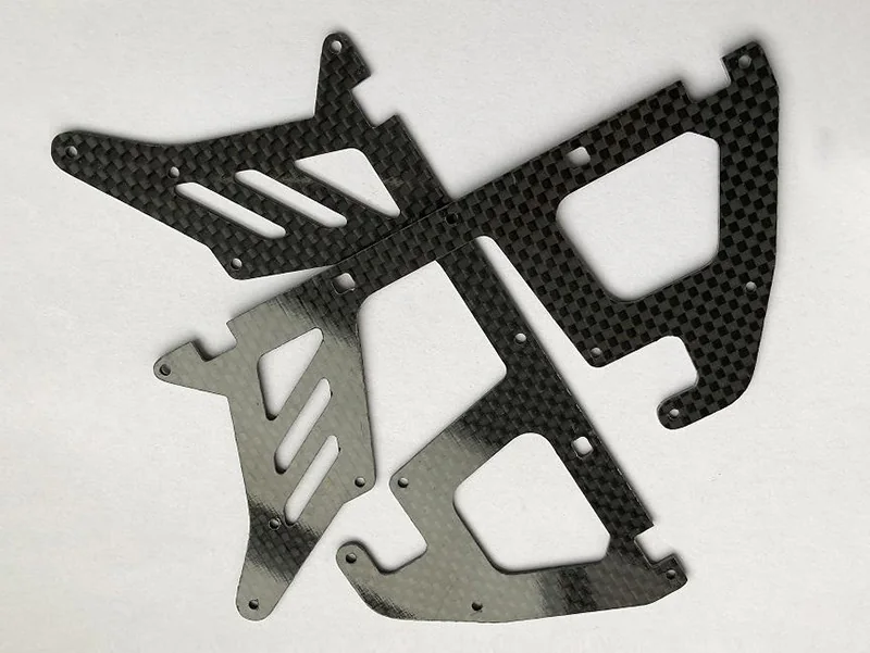
If the design already depends heavily on drilled details or precision cutouts, CFRPWorks custom-cut carbon fiber sheet service is the relevant manufacturing bridge—but the joint design still needs its own engineering evidence.
Thermal behavior: aluminum spreads heat; CFRP can control expansion
Kaiser reports thermal conductivity around 167 W/m·K for 6061-T6 sheet, plate and similar product forms. Aluminum is therefore useful when the structure also needs to move heat.
Conventional carbon/epoxy laminates are much more direction-dependent thermally. Through-thickness thermal conductivity can be especially low, while certain high-conductivity fibers or hybrid constructions can behave very differently. It is not accurate to give “carbon fiber” one universal thermal conductivity.
Thermal expansion also differs. Kaiser lists a linear coefficient of thermal expansion for 6061 near 23.6 µm/m·K over the stated range. Carbon fibers can have very low or negative longitudinal CTE, and a laminate can be designed for low in-plane expansion. The resin-dominated directions behave differently, so a finished CFRP part should not automatically be described as “zero expansion.”
This creates two different opportunities:
CFRP can be attractive when dimensional stability matters. Precision beams, optical structures, robotics and measurement systems may benefit from low mass and tailored thermal expansion.
Aluminum can be attractive when heat spreading matters. Electronics mounts, heat-sink structures and components near significant thermal loads may benefit from aluminum’s much higher thermal conductivity.
Hybrid assemblies need special attention because aluminum inserts and CFRP laminates can expand differently with temperature.
Carbon fiber and aluminum together: manage galvanic corrosion
CFRP does not corrode like aluminum, but carbon is electrically conductive. When carbon composite is electrically connected to aluminum in the presence of an electrolyte, the aluminum can become vulnerable to galvanic corrosion.
FAA AC 20-107B specifically notes the use of isolation layers, such as glass plies, between carbon composites and aluminum where needed.
A hybrid CFRP/aluminum design may therefore require:
- electrical isolation layers;
- compatible primers and coatings;
- sealed holes and edges;
- suitable washers, bushings or adhesive films;
- moisture drainage and sealing strategy;
- inspection of protective interfaces.
“Carbon fiber does not rust” is true in the narrow sense, but it is not a sufficient corrosion strategy for a mixed-material assembly.
Manufacturing and cost: compare process economics, not price per kilogram
Aluminum and CFRP usually reach the final geometry through very different process chains.
A low-volume aluminum part can often move quickly from CAD to billet or plate, CNC machining, drilling and finishing. Design changes may require only a new program or fixture adjustment.
A CFRP part may require material definition, ply design, mold or tooling, layup, cure, trimming, drilling, inspection and—in some cases—bonding or insert installation. Higher-volume composite processes can automate significant portions of that work, but the economics depend on geometry, material system, annual volume, quality requirements and cycle time.
This is why a universal statement such as “CFRP becomes cheaper than aluminum above 100 parts” is not defensible.
A useful cost comparison includes:
- engineering and laminate-development effort;
- nonrecurring tooling and fixtures;
- raw material and material utilization;
- cure or molding cycle time;
- trimming and secondary machining;
- inserts and joint hardware;
- inspection and scrap risk;
- finishing;
- repair and service requirements;
- the economic value of the mass saved.
The last item is often what changes the answer. A kilogram saved on a stationary industrial cover may have little value. The same kilogram on a UAV, robot arm, moving gantry or performance vehicle may affect payload, range, acceleration, motor sizing or energy consumption.
For a broader discussion of what actually drives a carbon-fiber quote, see Carbon Fiber Price: Why Quotes Vary by Material and Finished Part.
When CFRP is usually worth evaluating
CFRP deserves serious consideration when several of these conditions are true:
- the structure is mass-sensitive;
- deflection matters more than material price;
- principal load directions are known;
- the geometry can be redesigned around laminate behavior;
- lower moving mass improves dynamic performance;
- thermal dimensional stability matters;
- integrated composite geometry can remove brackets or separate pieces;
- production quality and inspection can be controlled;
- the business value of saved mass is measurable.
Typical examples include lightweight robot members, UAV structures, moving machine components, stiff panels and selected automotive or aerospace structures.
For application-specific examples, see Carbon Fiber Robot Parts and Carbon Fiber Automotive Engineering.
When aluminum may still be the better engineering choice
Aluminum often remains the better option when:
- the part has complex, uncertain or strongly multidirectional loads;
- local bearing and threaded features dominate;
- impact damage must be obvious and easy to assess;
- heat spreading is important;
- field repair or modification must be simple;
- welding is central to the assembly strategy;
- production volume is low and tooling cannot be justified;
- the design is changing rapidly;
- the achievable system-level mass saving has low economic value.
For a strength-limited metal part, moving from 6061-T6 to 7075-T6 may be worth evaluating before changing material systems. For a stiffness-limited part, remember that 7075 is much stronger than 6061 but only slightly stiffer; geometry may still have to change.
A practical decision sequence for replacing an aluminum part with CFRP
Before requesting a carbon-fiber version of an aluminum drawing, define the engineering job in this order.
1. Freeze the current aluminum baseline
Record:
- alloy and temper;
- part mass;
- critical dimensions;
- load cases;
- maximum allowed deflection;
- factors of safety;
- joint details;
- operating temperature;
- corrosion environment;
- production volume;
- current manufacturing and finishing route.
2. Identify what actually drives the redesign
Is the goal:
- lower mass;
- lower deflection;
- higher natural frequency;
- lower moving inertia;
- dimensional stability;
- corrosion resistance;
- appearance;
- integrated geometry?
If there is no quantified reason to leave aluminum, the composite redesign may add complexity without creating system value.
3. Redesign the load path for CFRP
Do not automatically copy the metal geometry. Identify primary load directions, bending axes, torsion, fastener locations, inserts and cutouts. Then define a laminate and section concept that puts fibers where they can work.
4. Compare at part level
Evaluate the proposed CFRP design against the aluminum baseline for:
- mass;
- stiffness and deflection;
- buckling;
- strength;
- joint allowables;
- impact;
- thermal behavior;
- inspection;
- manufacturing risk;
- total cost.
5. Define verification before release
For critical parts, decide which evidence is needed: material certification, coupon testing, first-article inspection, dimensional verification, load testing, NDI, environmental testing or assembly-level validation.
That keeps the decision tied to the finished part rather than to a material marketing number.
Frequently asked questions
Is carbon fiber lighter than aluminum?
For the same material volume, typical carbon/epoxy laminates are substantially less dense than 6061 or 7075 aluminum. Finished-part weight reduction is not fixed, because the required laminate, section geometry, inserts, joints and impact margins can change the amount of material required.
Is carbon fiber stiffer than aluminum?
It can be much stiffer per unit mass in a designed fiber direction. A balanced or quasi-isotropic laminate will not retain the full 0° unidirectional advantage in every direction. Compare the actual laminate and structural stiffness for the governing load.
Is 7075 aluminum stiffer than 6061?
Only slightly. 7075-T6 has much higher yield and tensile strength than 6061-T6, but both have an elastic modulus near 70 GPa. If a part is deflection-limited, changing alloy alone may produce little stiffness improvement.
Does carbon fiber handle impact better than aluminum?
There is no universal answer. Aluminum often dents and plastically deforms. CFRP can suffer matrix cracking or delamination that may be less visible. Impact energy, laminate design, geometry, inspection method and required residual strength determine which material is more appropriate.
Can carbon fiber be bolted to aluminum?
Yes, but the joint requires composite-specific bearing and clamp-up design, and the carbon/aluminum interface may need galvanic isolation where moisture or another electrolyte can be present.
Which is cheaper: carbon fiber or aluminum?
There is no universal break-even point. Aluminum often wins for low-volume machined parts because dedicated composite tooling and process development can dominate. CFRP can become economically rational when performance value, integrated geometry, automation or production volume offsets its higher process complexity.
Take the next engineering step
If you are evaluating an aluminum component for a CFRP redesign, start with the current drawing, alloy/temper, mass, load directions, allowed deflection, joints, operating environment and expected annual volume.
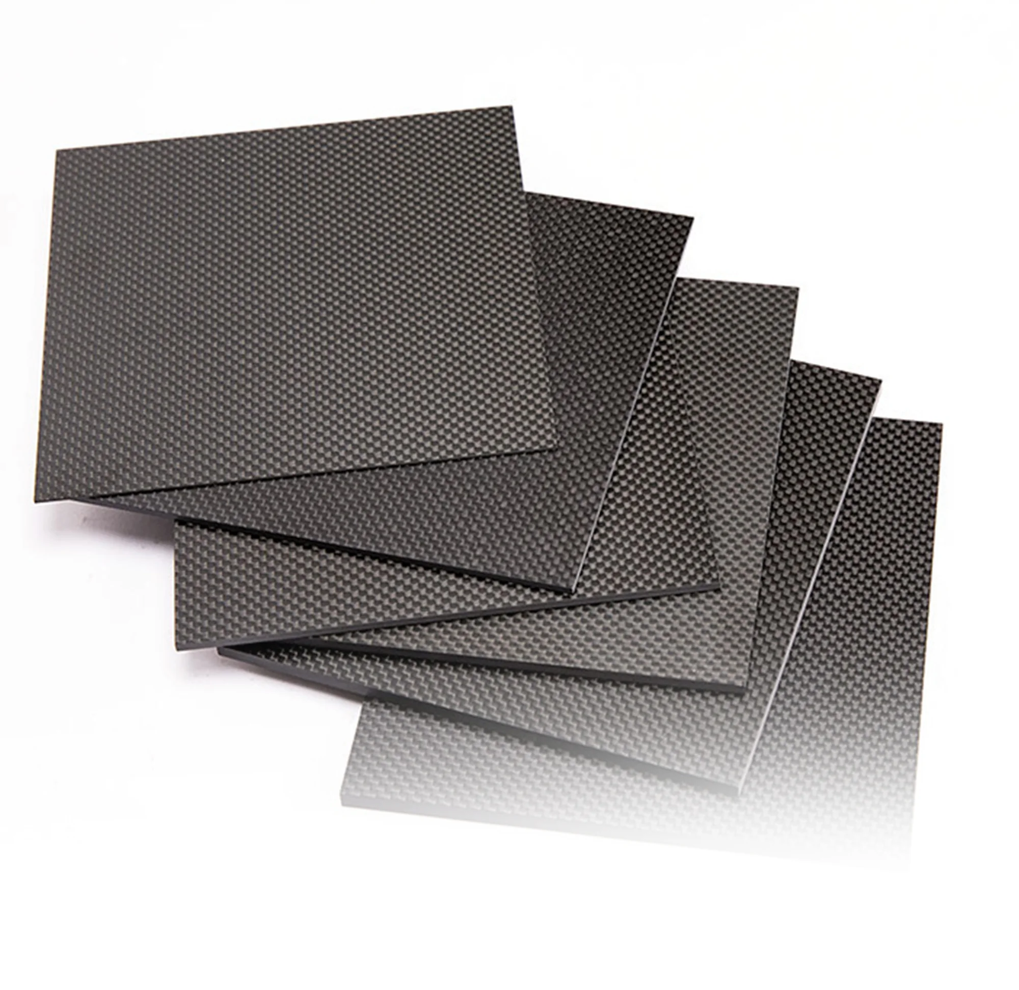
For sheet-based concepts, review Carbon Fiber Sheets. For a geometry-specific part, see Custom Carbon Fiber Parts and Custom Carbon Fiber Manufacturing.
The useful goal is not to “replace aluminum with carbon fiber.” It is to decide whether the part can be redesigned so that CFRP’s directional stiffness-to-weight advantage creates enough system value to justify a different material and manufacturing process.
References
- Toray Composite Materials America — TORAYCA™ T300 Data Sheet
- Kaiser Aluminum — 6061 Sheet, Coil & Plate Technical Data
- Kaiser Aluminum — 7075 Rod & Bar Technical Data
- FAA — AC 20-107B, Composite Aircraft Structure
- NASA — Highly Thermally Conductive Hybrid Carbon Fiber Polymer Composites
- Oak Ridge National Laboratory — Cost of Automotive Polymer Composites