
APPLICATIONS / INDUSTRIAL EQUIPMENT
Industrial Carbon Fiber Parts for Equipment, Fixtures and Jigs
Industrial equipment parts should be judged by real load, temperature, cycles and maintenance. CFRP can be evaluated where moving mass, stiffness or handling weight matters, but the decision belongs to the assembled machine, not to a material label.
Engineering application guide only; no stock size, fixture model or qualified machine component is claimed here.
Application guidance only. Material suitability depends on the actual geometry, interfaces, duty cycle and acceptance method.
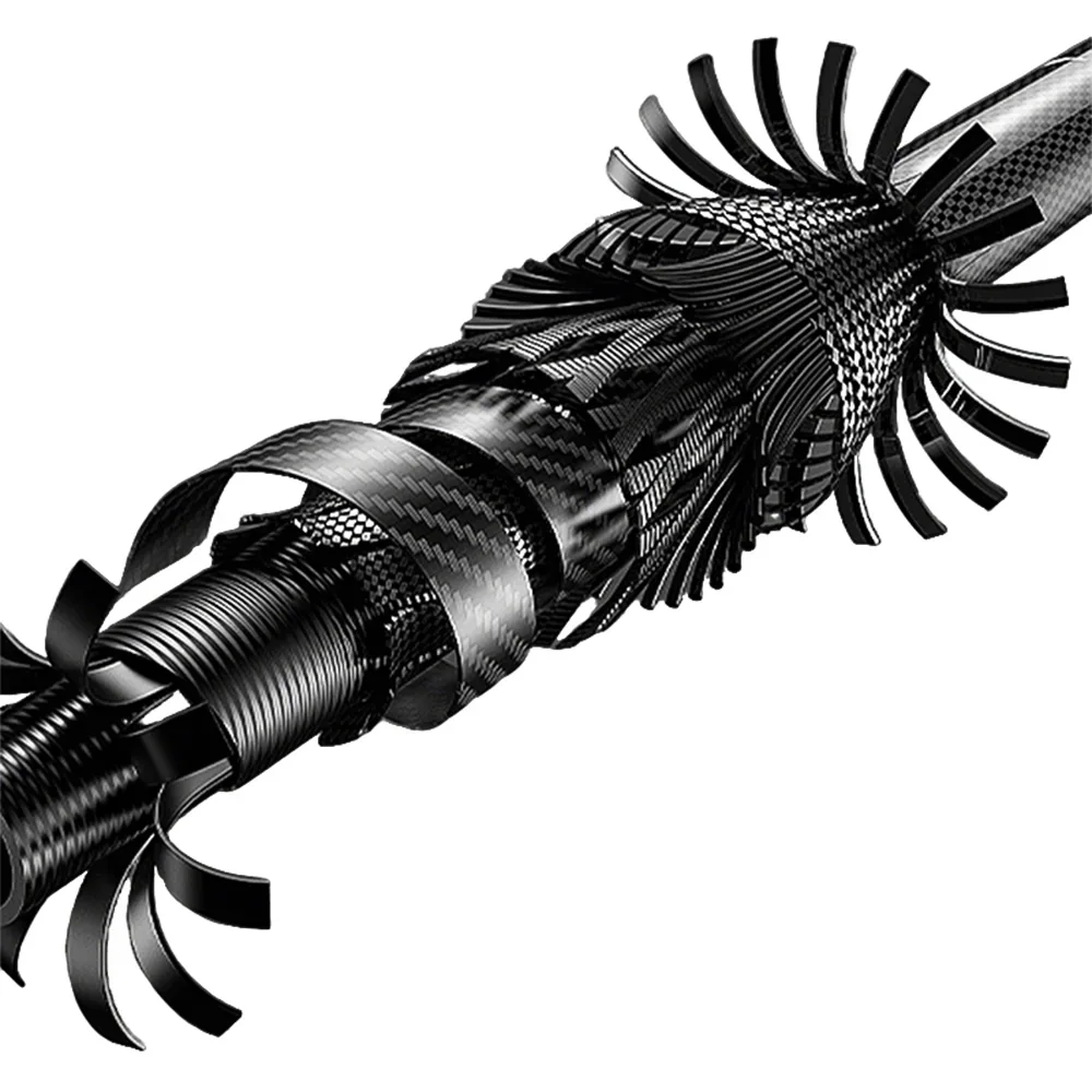
Generic machined composite example; not evidence of a CFRPWorks-qualified industrial equipment part.
01 / EQUIPMENT DUTY
Start with what the equipment component must do
A moving cross-member, stationary workholding jig and inspection support can all be industrial parts, yet their failure and acceptance criteria differ. Compare them by function before comparing materials.
01
Moving machine beam or gantry support
Lower moving mass may matter if stiffness, alignment and dynamic stability remain adequate.
CHECK
Travel speed, acceleration, resonance, maximum deflection, connection load and stop/impact case.
02
Assembly jig or workholding fixture
Reduced handling mass can help only when loaded datums remain accurate and durable.
CHECK
Clamp load paths, bushings, datums, loaded positioning and handling frequency.
03
Inspection or measuring support
A favorable stiffness-to-mass concept may suit accurately located frames.
CHECK
Sensor/datum accuracy, temperature variation and calibration method.
04
Industrial structural bracket or platform
A load-tailored beam or plate can be compared with a larger metal member.
CHECK
Fasteners, edge loads, impact cases, chemicals and replacement method.
05
Process fixture or tooling support
Repeated heating, cycling or process contact can influence material selection.
CHECK
Temperature, cleaning fluid, wear, clamp load and process constraints.
These are engineering scenarios, not claims that a specific CFRPWorks part is qualified for the listed machine duty. A drawing and an acceptance method are required before material selection.
02 / MATERIAL BASELINE
Compare the installed structure, not density alone
Carbon fiber is anisotropic: fiber direction, matrix, laminate architecture and geometry affect performance. A generic property cannot establish the stiffness or safety of an assembled machine component. Compare installed mass, tool-point deflection, cycle accuracy, joint wear, service time and total cost under the same load case.
01
CFRP laminate
Directional reinforcement can be useful when the load path is understood. Holes, out-of-plane loads and concentrated bearing may require local design changes.
02
Aluminum or steel
Often remains preferable where frequent machining, threaded interfaces, predictable ductile behavior, heat transfer or field repair dominate.
03
Hybrid structure
A composite span can be paired with metal load-transfer fittings, bearing seats or wear interfaces, but each joint still needs load, clamp and thermal verification.
The material decision becomes useful only when the same functional target, interfaces and acceptance test are applied to each candidate.
03 / DATUM CONTROL
Jigs and fixtures need more than low weight
Reducing handling weight is useful only if functional datums position the workpiece correctly under clamping and throughout service. Material stiffness cannot correct an inaccurately located bushing, clamp distortion or a joint that shifts under repeated loading.
Map the location scheme, pin and bushing loads, clamp paths, vacuum or mechanical contact points, and how operators release the workpiece. Replaceable metal wear pads or inserts may be appropriate at repetitive contact surfaces, but they must be designed as part of the fixture.
01
Locate
Define datums, pins, bushings and the workpiece reference scheme.
02
Clamp
Verify loaded positioning and distortion under real clamping forces.
03
Recheck
Measure repeatability after handling, transport and representative cycles.
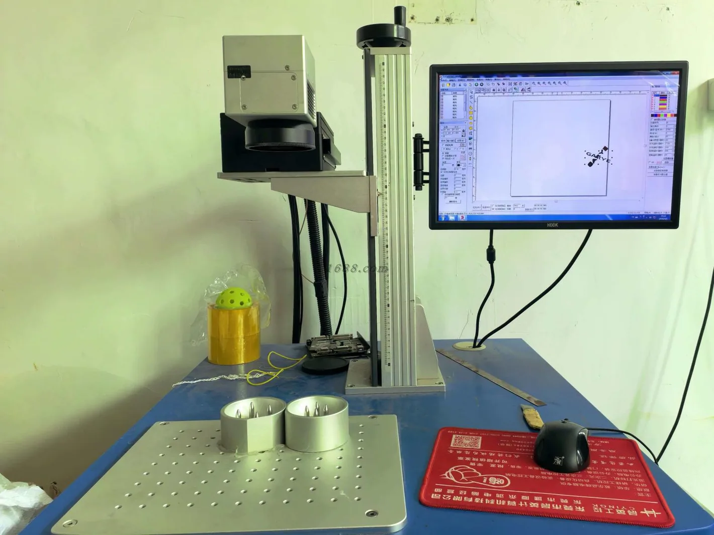
Factory-supplied measuring equipment shown as measurement context; no fixture-accuracy or vibration result is implied.
04 / ENVIRONMENT & DYNAMICS
Thermal drift and vibration are assembly-level questions
Composite thermal movement depends on laminate direction, resin, geometry and attachments. A published coefficient from one laminate cannot be copied into a different fixture design, and a steel or aluminum mount can move with the composite as one system.
Thermal behavior
Define the operating temperature profile and measure datum drift at the functional point. Do not substitute a generic “carbon fiber does not expand” claim for an assembled-system check.
Vibration and service
Mass distribution, bending/torsional stiffness, mounts, excitation frequencies and mode shapes determine response. Also review coolant, cleaners, oils, moisture, abrasion, electrical conductivity and any ESD strategy for the actual material system.
A lighter beam may shift natural frequencies without solving a machine vibration problem. The validation target must match the machine’s actual operating case.
05 / LOAD TRANSFER
Bolts, edges and wear can control the structure
A stiff composite beam can still lose alignment at a bolted, bonded or replaceable interface. Review how load enters the part, whether a local crush, peel, impact or fatigue case exists, and how a technician will inspect or replace the affected element.
Design the interface as deliberately as the span
Metal bushings, bonded reinforcements and sacrificial pads are possible responses at fastener holes or repetitive wear surfaces. Each adds its own mass, cost, tolerance stack and verification requirement.
If the assembly is frequently disassembled or must tolerate rough contact, a metal design may be easier to maintain. That trade-off belongs in the application decision rather than being treated as a failure of the composite concept.
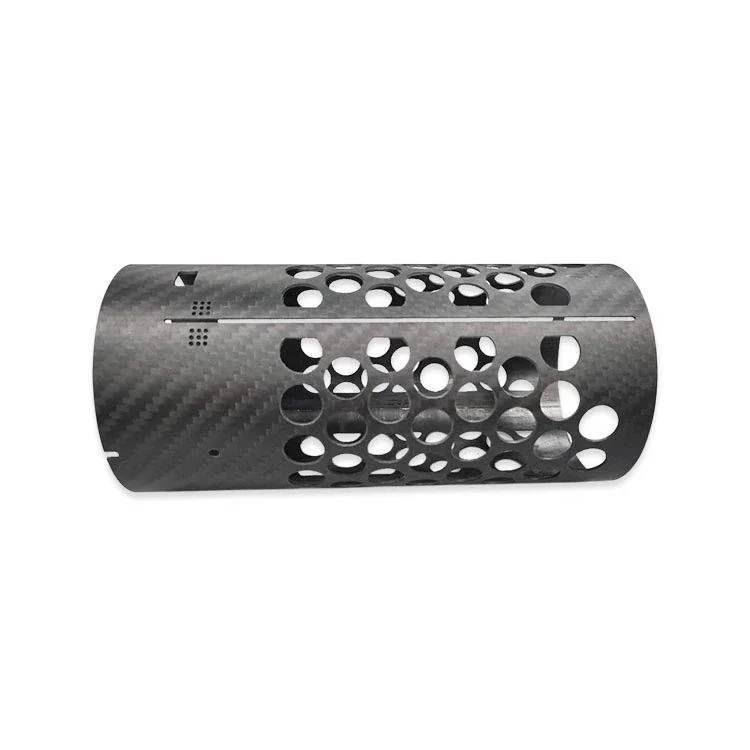
CFRP component example showing machined openings and interface-rich geometry. The image illustrates design context only; machine duty, loads and qualification must be verified for the actual application.
06 / MATERIAL FORM
Continuous-fiber laminate is not the same as a carbon-filled print
Some industrial fixture concepts use thermoplastics filled with short carbon fibers, while laminated plates or tubes use continuous reinforcement. Both can be useful in the right context, but they are not interchangeable materials.
CONTINUOUS LAMINATE
Fiber path is designed through the part
Evaluate laminate orientation, layer architecture, edges, holes, joint loads and service temperature for the proposed geometry.
CARBON-FILLED PRINT
Short-fiber orientation follows the printing process
Evaluate fiber length/orientation, layer adhesion, print direction, temperature behavior, repeatability and the same functional load case.
State the proposed production form, load orientation and accepted test method before comparing them. A single generic “carbon fiber” strength figure hides the differences that matter.
07 / INQUIRY INPUTS
What to provide for an industrial equipment inquiry
A short requirements package turns a material question into an engineering discussion. Unknown loads, tolerances or tests should be marked as assumptions with the next measurement identified, not replaced by invented specifications.
01
Assembly context
Machine type, whether the part moves or stays fixed, mating equipment and operator-access or guarding requirements.
02
Geometry and load
CAD/STEP model, drawing revision, section limits, bolt patterns, spans, static/peak loads, acceleration, clamping and possible shock cases.
03
Accuracy and operation
Allowable deflection at the functional point, positional or datum tolerance, cycle count, vibration frequency and recalibration interval.
04
Environment and service
Ambient/process temperature, coolant and cleaning agents, electrical/ESD constraints, inspection access and consumable/wear elements.
05
Acceptance and purchasing
Assembly-level test method, sample or production phase, expected quantity range, traceability needs and confidentiality requirements.
The first task is to determine what must be verified; only then can a proposed geometry, interface and supply route be evaluated.
08 / DECISION QUESTIONS
Frequently asked questions
Are carbon-fiber structural components always better than aluminum for equipment?
No. The result depends on mass limits, span, stiffness in the relevant directions, joints, cost and service. Aluminum may be preferable where frequent machining, changes or threaded interfaces dominate.
Can carbon fiber be used in a jig or fixture?
It can be evaluated as a structural option. Clamp and datum interfaces, wear parts, positioning repeatability and inspection after handling must be checked for the actual jig.
Can carbon-fiber tooling reduce thermal drift or vibration without testing?
Not automatically. Laminate architecture, mounting, equipment temperatures, frequency response and the full assembly determine those outcomes. A measurement plan is needed.
Is a 3D-printed carbon-filled jig the same as a continuous laminate?
No. Fiber length, orientation, matrix, printing or lamination process and loaded geometry differ. Compare tested parts at equivalent loads and service conditions.
What makes an industrial carbon-fiber inquiry actionable?
An assembly drawing, real load and duty data, mating interfaces, target deflection or datum accuracy, environment, inspection method and project stage allow a focused technical discussion without assuming unproven specifications.
NEXT STEP
Move from a material idea to a comparable load and measurement plan
Describe the equipment, component function, mounting, load or measurement requirement and service environment. The useful next step is to define how a proposed laminate, metal assembly or carbon-filled printed fixture would be compared, not to assume one material is already qualified.