Source context: Mitsubishi Chemical — Carbon Fiber Manufacturing Method.
Carbon fiber is made by converting a suitable carbon-rich precursor into fine reinforcing filaments through controlled thermal treatment. A finished carbon-fiber component requires a separate manufacturing sequence: the fibers are arranged, combined with a matrix such as resin, consolidated into the intended shape and verified against a design.
These are two related but distinct production chains: the output of Chain A becomes an input, directly or after textile preparation, to Chain B. A company that makes carbon fiber tow may not make finished panels, and a company that fabricates composite parts does not necessarily operate a precursor-to-fiber production line. Understanding that boundary helps engineers ask the right questions about materials, manufacturing scope and evidence.
Two manufacturing chains, two different outputs
| Chain | Starts with | Typical transformation | Output |
|---|---|---|---|
| A. Carbon-fiber production | Spun precursor, commonly PAN or certain pitch-based materials | Stabilization, carbonization, possible further heat treatment, surface finishing | Carbon filaments or tow ready for textile or composite processing |
| B. Composite-part production | Carbon reinforcement and a selected matrix system | Layup or preforming, impregnation when needed, consolidation, cure or equivalent matrix processing, finishing | A cured or consolidated CFRP sheet, structure or finished component |
The stages shown are a conceptual map—not an instruction sheet or a universal recipe that can be applied to an arbitrary fiber grade or resin. Process sequences and controls differ by fiber precursor, polymer system, product geometry and qualification requirements.
Chain A: Turning a precursor into carbon fiber
1. Prepare and form the precursor
Many commercial carbon fibers begin with polyacrylonitrile (PAN), an organic precursor that is spun into continuous filaments. Selected pitch-based precursors provide another route. Producers also control filament formation and subsequent processing to meet a particular grade’s requirements; the precursor label alone cannot predict every resulting property.
At this point the material is not yet the carbon reinforcement that will appear in a cured laminate. It still needs controlled conversion that changes its chemistry and structure. The precise conditions are specific to the precursor and production design.
2. Stabilize the precursor
For a conventional PAN-derived route, filaments undergo oxidative stabilization before higher-temperature treatment. This controlled stage prepares them to maintain useful filament form during later conversion instead of behaving like an ordinary polymer exposed to severe heat.
This chemistry matters because carbonization needs a precursor that can retain a useful filament shape. Stabilization is not the same as curing a composite resin. It happens upstream, while a carbon-fiber producer is still making reinforcement. A finished-part manufacturer normally receives material that has already passed through this stage.
3. Carbonize the stabilized material
Carbonization uses carefully controlled thermal processing in a non-oxidizing environment to convert the stabilized precursor into carbon-rich fibers. Noncarbon constituents are removed as carbon-rich structures develop; the details depend on chemistry and processing, so a simple ‘burning off plastic’ analogy is misleading.
The result is a reinforcement with properties linked to its chemistry, microstructure and processing history. It is misleading to attach a single temperature or mechanical result to every carbon fiber: manufacturing conditions and the resulting grade vary. Material-specific producer documentation is needed for any exact numerical claim.
4. Apply further heat treatment when appropriate
Some fiber routes include additional high-temperature treatment often discussed as graphitization. Such treatment can influence the ordering of carbon structures and may be used for particular target properties. It is not mandatory for every commercially useful carbon fiber; a process description that treats it as universal misstates the sequence.
“More heat” is not a substitute for reading the grade’s actual tensile modulus, strength, handling and application constraints. The relevant producer datasheet should identify grade-specific performance and testing conditions. A phrase such as ‘graphitized’ alone does not establish a cured component’s design limits.
5. Treat the surface, apply sizing and form tow
Producers may modify the fiber surface and apply a thin sizing finish to support handling and compatibility with a subsequent matrix system. The treated filaments are bundled or organized into forms such as tow, which may later be woven, spread or converted into tape.
Sizing is not the same thing as the bulk resin that will hold a laminate together. Sizing is a thin coating that may support handling and later matrix adhesion, subject to chemical compatibility. The latter forms the matrix throughout a finished composite. Confusing these stages can lead to inaccurate material specifications.
At the end of Chain A, the output is reinforcement. A spool of carbon fiber is not automatically a rigid structural sheet.
The handoff: from fiber supplier to composite manufacturer
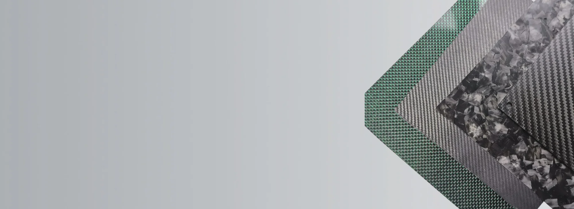
Carbon reinforcement can be sold or processed as continuous tow, dry woven fabric, unidirectional material or prepreg. Prepreg is reinforcement pre-impregnated with a specified resin system and held at an intermediate processing state. It is not necessarily already cured into its final structural form.
The handoff matters because material identity is not just the word “carbon.” A composite designer needs the reinforcement form and traceable grade, fiber orientation, matrix system, processing restrictions and how each material handoff will be documented. A material certificate for the fiber does not establish that a later laminate was fabricated and inspected correctly.
Chain B: Making a carbon-fiber composite part
1. Translate the design into material and layup requirements
The part’s intended duty comes first: loads, deformation limits, geometry, environment, finish and connection details. Reinforcement can be selected and arranged so that its fibers support the relevant directions of loading. Matrix selection is another design choice, with temperature and processing constraints that must be evaluated independently of fiber properties.
A drawing of a flat decorative cover and a structural mounting bracket can lead to different laminate schedules even when their visible surfaces use similar carbon-fiber fabric. Visible weave alone does not reveal the internal reinforcement stack.
2. Place reinforcement into the required geometry
Depending on the design and process, dry fabric, unidirectional plies or prepreg may be laid into a tool or otherwise formed into a preform. A draped visible layer may serve appearance, while internal structural plies must follow the actual load path. The target is not simply to place carbon fiber in a mold. The manufacturer must control orientation, layer sequence, fit and other variables that determine the actual structure.
For example, a flat panel with a defined bending direction may call for a different ply arrangement than a curved cover constrained mainly by surface appearance. Neither case can be qualified from the word “carbon fiber” alone.
3. Introduce or manage the matrix
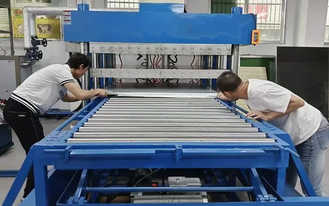
Several industrial approaches exist; they are alternatives, not successive steps that every factory performs:
| Route | How the reinforcement and matrix come together | Main selection considerations |
|---|---|---|
| Prepreg layup | Resin is already incorporated in a controlled intermediate | Storage/handling conditions, layup and validated consolidation/cure |
| Resin infusion or vacuum-assisted processing | Liquid resin is introduced to a dry reinforcement arrangement | Fill quality, geometry, matrix viscosity and process control |
| Resin transfer molding | Reinforcement is placed in tooling and resin introduced using an appropriate closed-mold method | Tooling, flow path, repeatability and part design |
| Other molding or thermoplastic-composite methods | Reinforcement and matrix are combined using a different material-specific system | Matrix behavior, heating/cooling, geometry, production objectives |
An autoclave may be appropriate for a particular prepreg system or application, but it is not an essential step for every CFRP component. Nor does the choice of a named process prove the resulting part meets a strength or quality target. The existence of an autoclave—or any other named tool—does not establish an individual part’s acceptance. Records about the material and finished part still have to match the specification.
4. Consolidate and form the matrix
With a thermosetting resin, controlled cure converts the matrix into a hardened network. Thermoplastic composites use different heat and consolidation/cooling behavior; calling both processes an identical “resin cure” would be imprecise.
The selected route must control voids, incomplete impregnation, misaligned reinforcement and geometry-dependent defects. Some flaws are visible; others need more suitable verification. Specific temperatures, pressures and cycle durations cannot be transferred from a generic online guide to an unspecified product or resin system. They require supplier instructions and validated manufacturing parameters.
5. Finish and verify the component
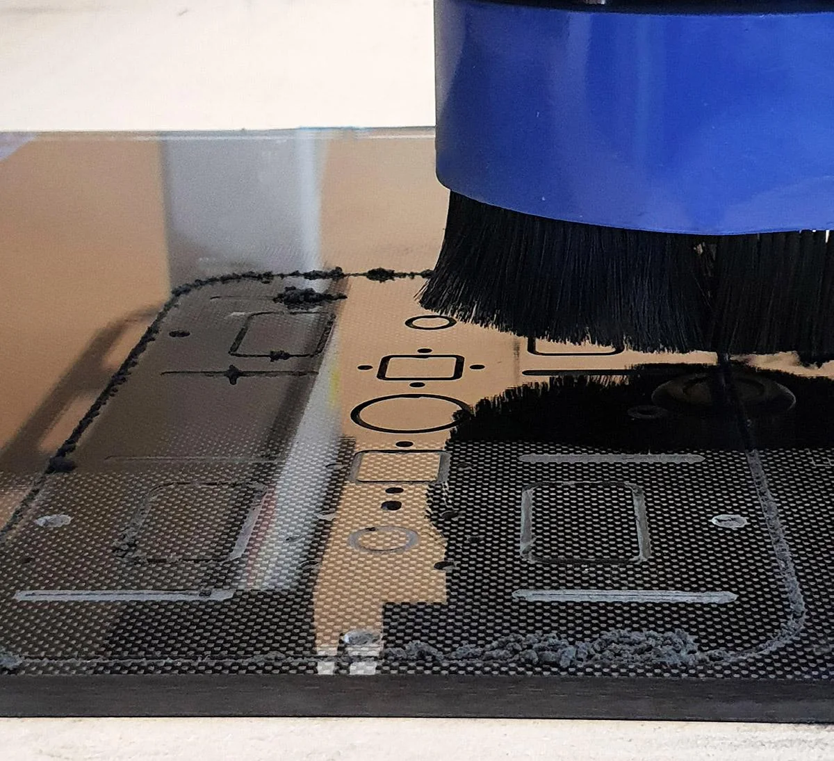
After consolidation, a part may require demolding, trimming, hole machining, joining or surface finishing, depending on its design. Finishing introduces its own dimensional and edge-quality requirements. Machining produces carbon-containing dust and can damage edges if the tooling and controls are unsuitable. Manufacturing and inspection plans need appropriate worker controls and part-specific acceptance, rather than inferring structural quality from a clean surface.
Inspection needs to follow the actual buyer specification. It might involve dimensions, visual condition, material/process records or suitable mechanical or nondestructive tests where justified. An incoming fiber certificate, a process record, a laminate coupon result and a completed-part inspection each answer a different question. None can automatically substitute for the others when the requirement is part-specific.
How to compare process claims before specifying a part
The phrase “carbon fiber manufacturing” could refer to precursor conversion, textile preparation, prepreg production, part lamination or downstream machining. Rather than assume one supplier operates all stages, request evidence for the specific scope being offered.
For a practical engineering review, define:
- Requested output: dry reinforcement, flat stock, a formed laminate or a finished drawing-controlled component.
- Design input: geometry, expected loads, orientation constraints and relevant temperature or chemical exposure.
- Material system: required fiber form and grade where applicable, compatible resin/matrix and any restricted substitutions.
- Manufacturing boundary: which steps are performed by which party, and what records transfer between them.
- Acceptance basis: dimensions, appearance, documentation and any application-appropriate tests or inspection criteria.
For a non-load-bearing appearance panel, visible finish and fit may be central. For a safety-critical structural part, qualification, load cases and traceable testing demand a much deeper evidence package. The level of review must match the actual engineering risk. If the component carries critical loads, a visual photograph or generic “autoclave-made” claim is insufficient. Appropriate verification follows actual risk and design function.
Frequently asked questions
Is carbon fiber made from plastic?
Many carbon fibers are made from a PAN polymer precursor that is chemically and structurally transformed through thermal treatment. The resulting carbon-rich filament is not simply a strand of ordinary unconverted plastic. A finished CFRP part separately combines carbon reinforcement with a matrix, often a polymer.
Is graphitization required to make all carbon fiber?
No. Additional higher-temperature treatment is a route used for certain target fiber characteristics. The appropriate sequence and achieved properties depend on precursor, grade and producer controls.
Are a carbon-fiber factory and a composite-parts factory the same thing?
Not necessarily. Producing continuous carbon filaments from precursors and making finished components from purchased reinforcement are separate industrial activities. Some organizations may participate in more than one stage, but a business claim of vertical integration needs first-party proof.
Does prepreg mean the finished part is already cured?
No. Prepreg is an intermediate reinforcement-and-resin material intended for further processing. Storage, layup, consolidation and cure conditions are governed by the particular prepreg system and part specification.
Does every carbon-fiber part require an autoclave?
No. Autoclave processing is one possible route for selected systems, while other established processing approaches exist. Material, geometry, performance requirements and verified controls determine the appropriate method.
Does a carbon-fiber weave prove the finished part’s strength?
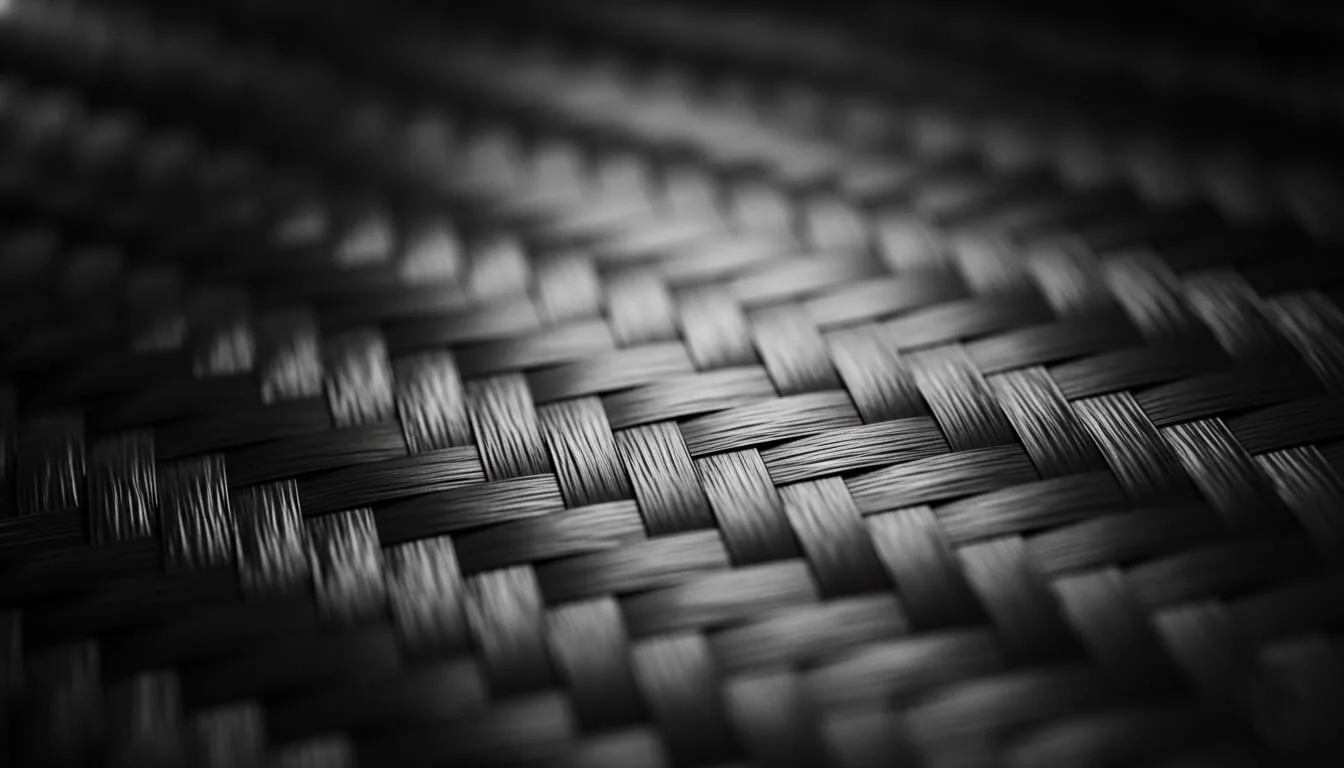
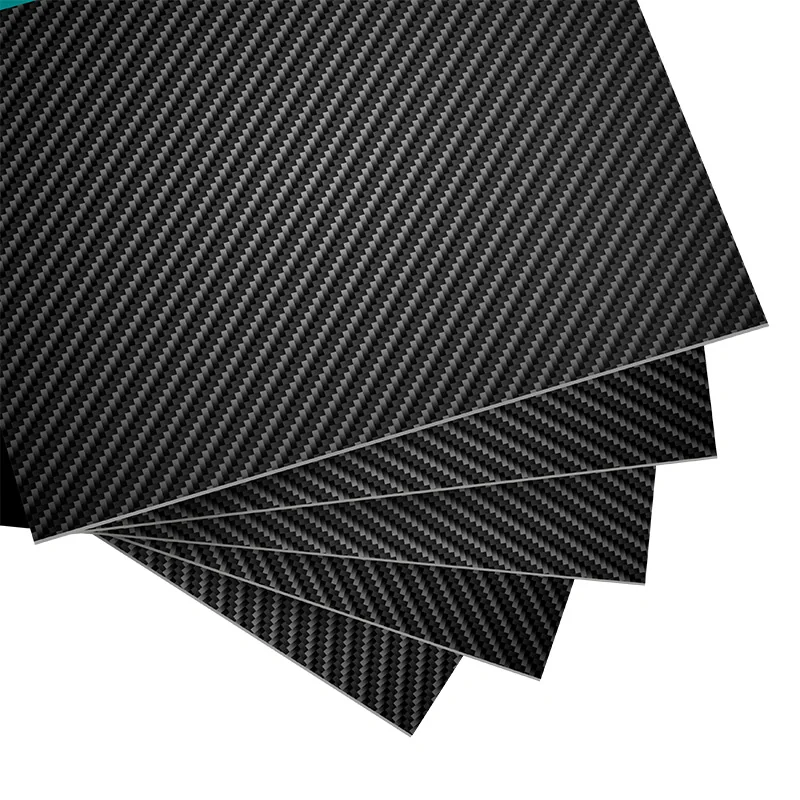
No. The weave describes one aspect of reinforcement format. Part performance also depends on hidden layers, orientation, matrix, manufacturing defects, geometry and testing conditions.
From process understanding to a manufacturing requirement
To turn process knowledge into a part specification, prepare a drawing or project brief covering the intended output, material constraints, geometry, process responsibilities and acceptance criteria. For drawing-led composite parts, explore our custom manufacturing overview. To continue learning, browse the carbon fiber resources.
Related technical guides: What Is Carbon Fiber? · Types of Carbon Fiber. Related capability: Carbon Fiber Fabrication.