
APPLICATIONS / ROBOTICS & EOAT
Carbon Fiber Robot Parts: Engineering Choices for Robotics and EOAT
In robotics, the useful question is not simply whether carbon fiber is lighter than metal. It is whether a moving structure can meet stiffness, interface, duty-cycle and inspection requirements with a lower assembled mass.
Evaluate the finished assembly under the same loads, geometry constraints and acceptance tests. A material datasheet or weight-saving percentage is not a robot-level result.
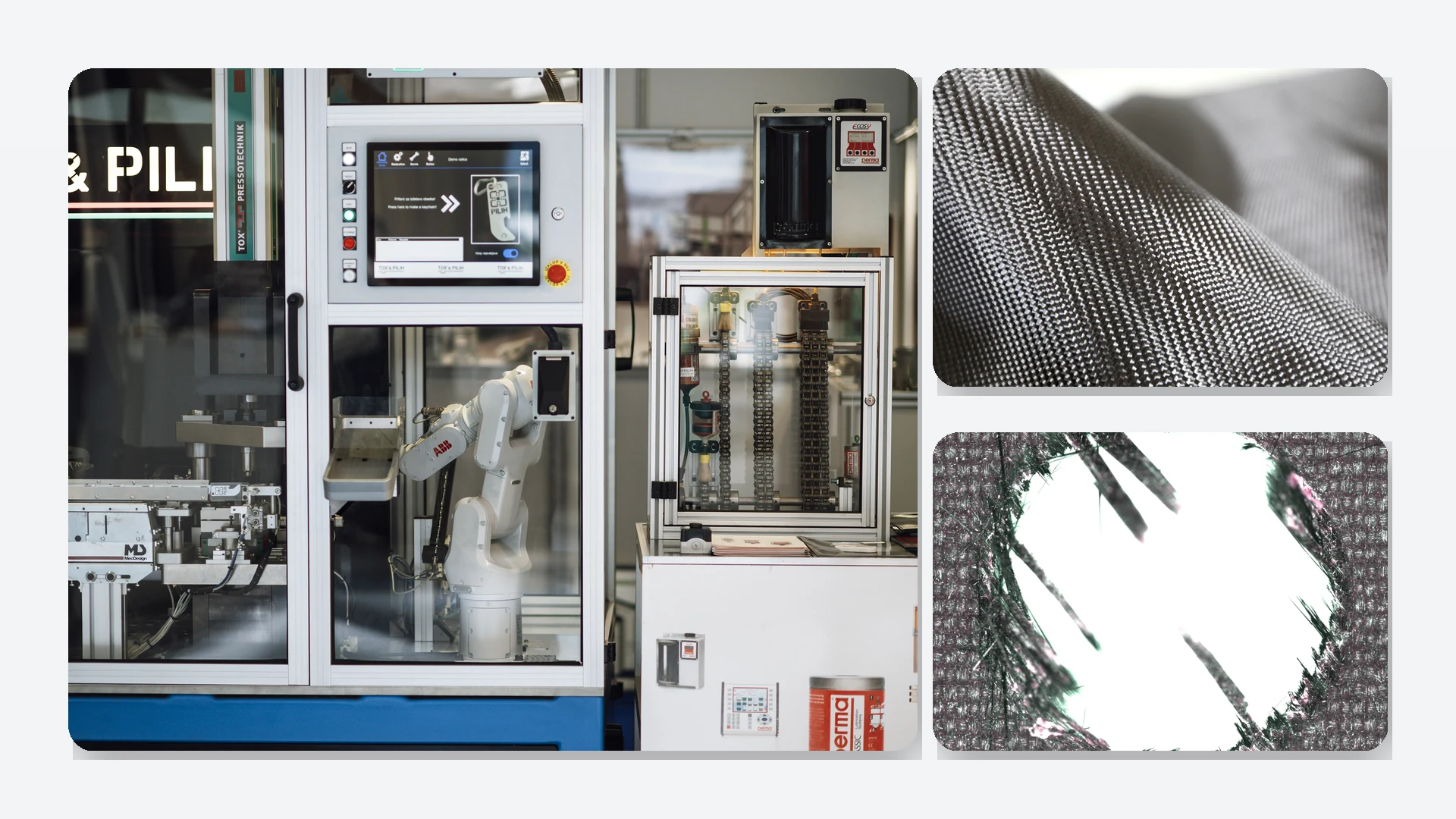
Licensed illustrative robotics image; not a CFRPWorks customer case, qualified robot component or tested-performance claim.
Start with the moving-system constraint
A composite concept is easier to judge when the robot-level constraint is named before the material. Four questions usually expose whether the structure deserves further evaluation.
01
Moving mass
Which portion of the tool or link moves, and how far is its mass from the wrist or joint axis?
02
Load path
Where do bending, torsion, clamp force, impact and emergency-stop loads actually enter the structure?
03
Interface
Which flange, insert, bearing, fastener or gripper interface transfers the local load into the laminate?
04
Acceptance
What tool-tip deflection, alignment, inspection or validation method will decide whether the assembled tool is acceptable?
POSSIBLE STRUCTURAL ROLES
Where carbon fiber could fit in a robot
Different robotic components ask different things of a laminate. Carbon fiber may serve as a structural member while bearings, actuators, contact pads and fasteners keep their own specialized roles.
Long-reach EOAT beam
Mass far from the wrist increases moment and can complicate alignment during acceleration.
Check: tool-center offset, combined tool/object mass, suction layout, peak acceleration, cantilever deflection and support.
Gripper support frame
A structural frame can protect jaw alignment without assigning wear or contact duty to an exposed laminate edge.
Check: clamp-force path, local bearing, finger wear surfaces, force direction and repeated jaw alignment.
Robot or delta-arm link
A directional laminate may suit a long member once axial, bending and torsional loads are established.
Check: joint-fitting loads, ply direction, torsion, natural frequency and stop/collision cases.
Sensor / inspection support
Stable sensor location can matter more than minimum weight in measurement and inspection tasks.
Check: position drift, vibration, alignment interfaces, cable routing and environmental exposure.
These are engineering roles to evaluate, not a catalog of qualified CFRPWorks robotic products. Each configuration needs its own dimensional, load and acceptance review.
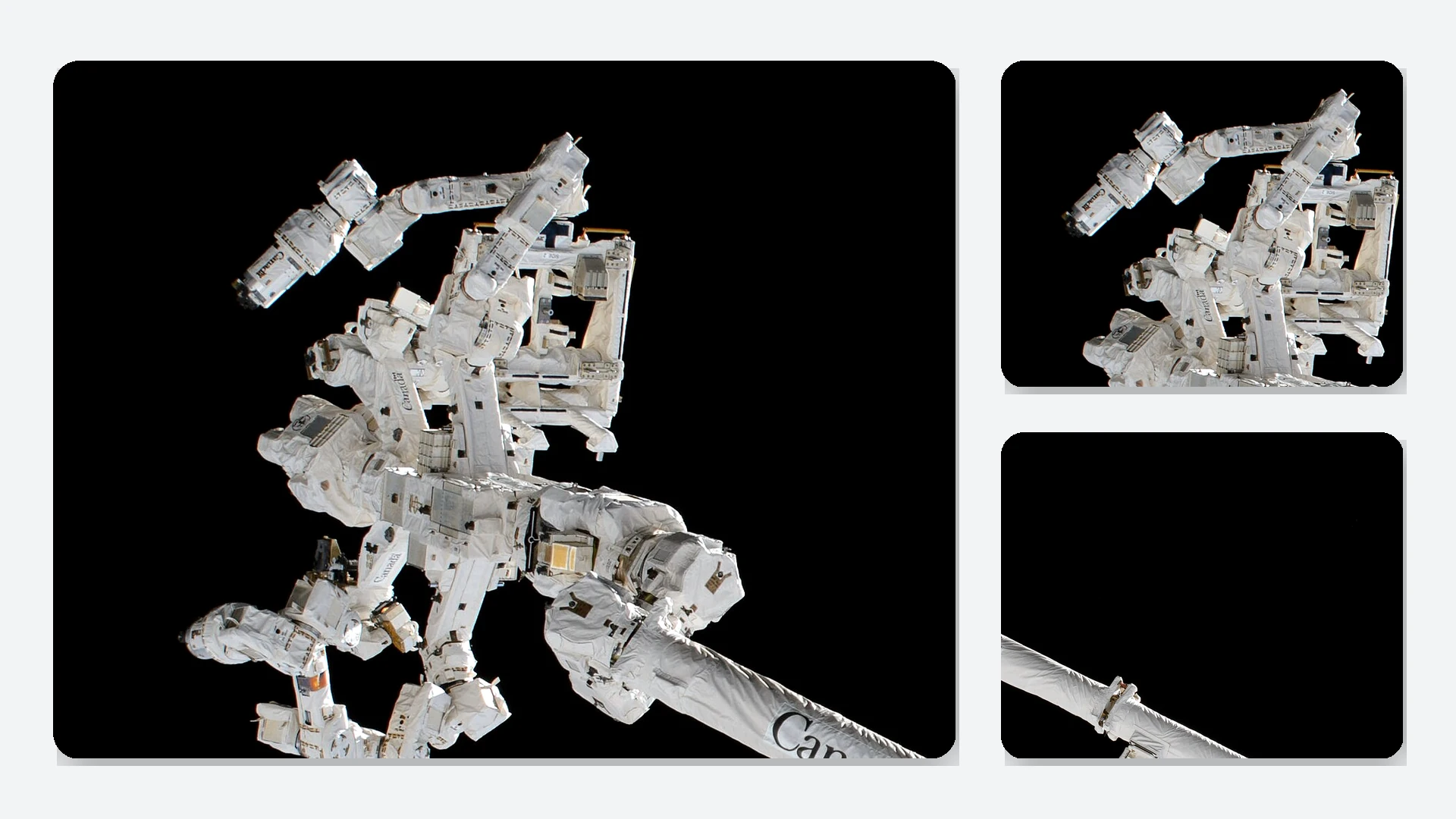
Illustrative EOAT context. Interface geometry, handled mass and robot limits must be reviewed for the actual system.
Tool weight is not the same as available robot payload
An EOAT assembly includes more than its structural frame: fittings, actuators, tubing, cables, vacuum components and the handled object all contribute to the load. Mass farther from the wrist also changes rotational inertia and moments.
SYSTEM CHECK
Structure + hardware + services + handled object + offset / inertia
Review this complete condition against the robot manufacturer's payload, center-of-gravity and inertia limits, together with acceleration, braking, reach and safety conditions.
A lighter structural member may create margin when moving mass is the dominant constraint, but it does not automatically change the robot's allowable payload or motion profile. Cycle-time and energy effects have to be measured at system level.
Material choice follows the load path
Carbon-fiber reinforced polymer is directionally reinforced. Geometry, layup, supports and local interfaces can matter as much as the nominal fiber or resin.
COMPOSITE SPAN
Carbon fiber: useful when directional stiffness and moving mass justify the redesign
A long member with established bending, axial and torsional loads can be evaluated as a laminate rather than treated as a direct metal copy. Off-axis, through-thickness and concentrated joint loads still need explicit design attention.
Aluminum remains practical when interfaces dominate
Many machined interfaces, evolving hole patterns, moderate stiffness targets and frequent design changes can favor a metallic structure.
Steel remains useful at compact, wear-intensive joints
Highly loaded or wear-critical local hardware may stay metallic even when a longer span is composite. Hybrid concepts need deliberate load transfer.
Compare total assembly mass, measured tool-tip deflection, shock tolerance, service access and replacement cost under the same functional conditions. Do not treat one material as a substitute for every surface or mechanism.
JOINTS & INTERFACES
The connection can decide whether the concept succeeds
A robot link or EOAT frame meets a wrist flange, bearing housing, actuator or gripper at a concentrated attachment. Holes, unsupported bolt pressure, edge distance and uneven clamp force can create failure or drift modes that a simple beam calculation does not capture.
01 · Load transfer
Identify the peak force and moment directions reaching each bonded fitting, bolt group or insert.
02 · Local compression & bearing
Check repeated clamp pressure and bearing loads instead of assuming lengthwise laminate strength covers them.
03 · Impact & wear
Define emergency-stop or collision cases, plus replaceable wear surfaces where contact is unavoidable.
04 · Environment
Review temperature, moisture, chemicals, adhesives and mixed-material contact for the actual installation.
05 · Inspection
Decide how operators will recognize damage or joint movement after an unusual stop, collision or service event.
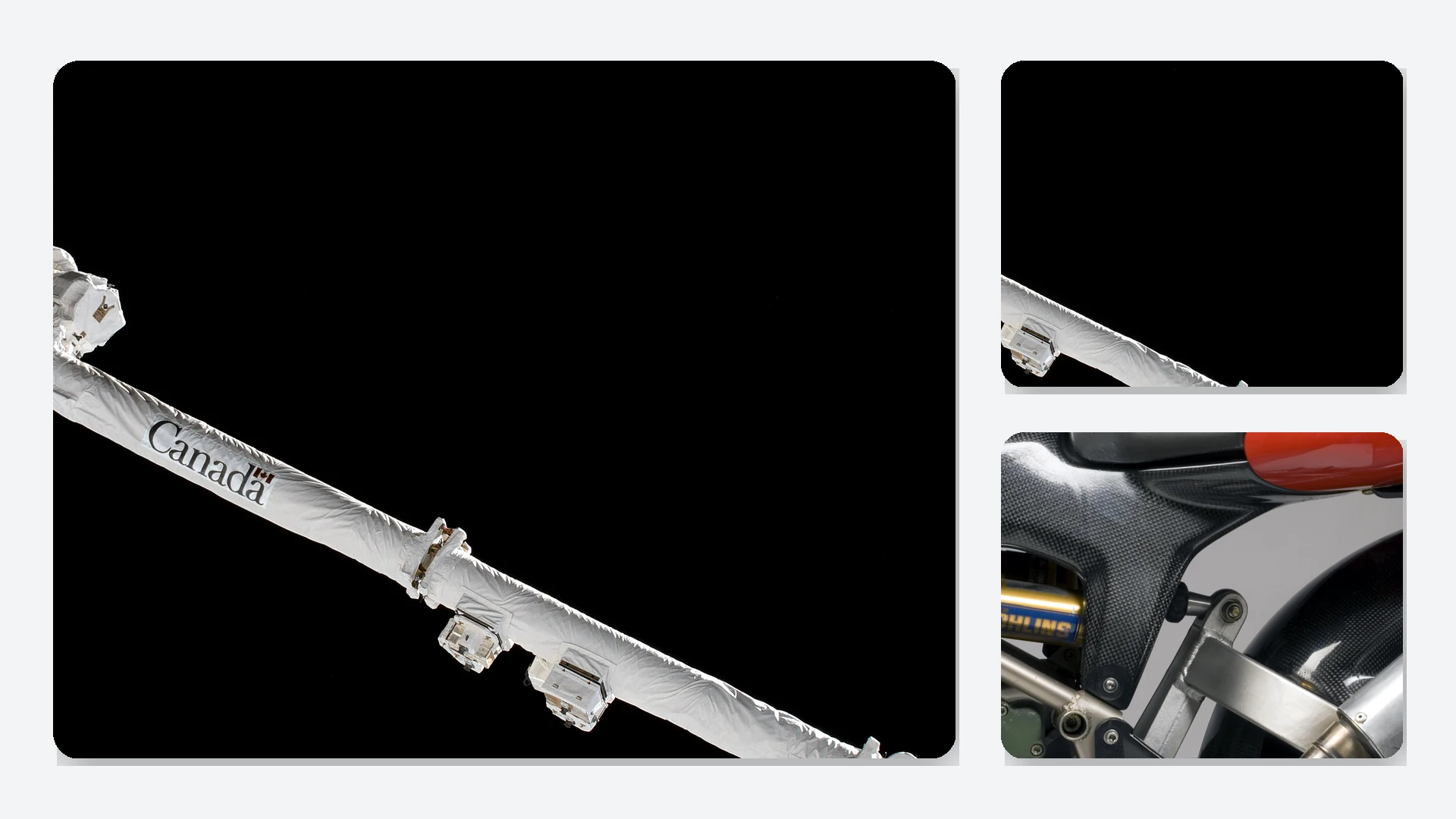
Licensed illustrative arm-link detail; not evidence of a CFRPWorks manufactured robot link or validated interface design.
Verify the assembled tool, not only the laminate
A coupon strength value cannot establish tool-center accuracy, fatigue life, robot compatibility or payload acceptance for the finished assembly. Acceptance criteria should connect the part to its intended duty.
01
Define the duty
Document loads, reach, acceleration, braking, cycle conditions and any credible stop or collision case.
02
Define the measurement
Use the receiving engineer's target for tool-tip deflection, alignment, repeatability or interface condition.
03
Exercise the assembly
Where appropriate, plan proof loading, representative motion cycles, vibration checks or environmental exposure.
04
Inspect after the event
Include a practical damage-inspection method for unusual stops, impacts, service work or acceptance testing.
The robot OEM's limits, the application's actual load cases and the receiving engineer's acceptance criteria remain the governing references. A nominal fiber grade or vendor example is not functional qualification.
What to include when discussing a robotics project
A useful inquiry separates the part being considered from the complete automation system. Share what is known and label what is still an assumption.
01 · Application & robot model
Task, robot mounting interface, handled object, and whether the target is a link, gripper frame, sensor support or EOAT structure.
02 · Geometry
CAD/STEP model or dimensioned drawing, assembly envelope, hole and fitting patterns, plus restricted-access areas.
03 · Operating loads
Static and peak loads, complete tool/object mass, center of gravity, acceleration, braking and impact or emergency-stop assumptions.
04 · Acceptance
Target tool-tip deflection, alignment or repeatability, inspection method, duty cycles and relevant environmental exposure.
05 · Commercial scope
Estimated annual quantity, prototype-versus-production objective, finish or assembly needs, and third-party interface or IP constraints.
Unknown loads, dimensions or duty conditions should remain marked as assumptions. Those uncertainties define the next engineering question; they should not become promised specifications.
Robotics carbon fiber: common engineering questions
Does a carbon-fiber end effector automatically increase robot payload?
No. The complete tool, gripped object, moment arm, inertia and the robot manufacturer's limits determine whether a given load is acceptable. Reducing one structural component's mass is only one input.
Is a carbon-fiber robot arm always stiffer than an aluminum arm?
No. Stiffness depends on geometry, fiber orientation, laminate, joining and load direction. Compare complete parts under the same bending, torsion and interface conditions.
Can carbon-fiber grippers use metal fasteners and fittings?
They can be designed with bonded or mechanical interfaces, often including metallic load-transfer elements. The joint still has to be checked for localized bearing, clamping and operational loads.
Is carbon-filled 3D-printed plastic the same as a laminated carbon-fiber structure?
Not necessarily. Fiber length and orientation, polymer, process and resulting part properties can differ considerably. The desired load path and qualification plan determine what is appropriate.
NEXT ENGINEERING STEP
Discuss Application Requirements
Identify the moving member and complete interface, share its load case and acceptance method, and flag the assumptions that still need measurement. That is the basis for comparing a carbon-fiber concept with the metallic baseline.